This thread has been locked.

If you have a related question, please click the "Ask a related question" button in the top right corner. The newly created question will be automatically linked to this question.

Fusion GUI using GPI to set UCD90160 system reset

Other Parts Discussed in Thread: UCD90240, UCD90160

If I use three GPI pins to control the system reset,as below:

But one of the three GPIs, GPI3 only set Active High, doesn't set Special Behavior,as below

Then what will happen? Does only GPI1 and GPI2 control system reset and GPI3 can be ignored?Does GPI3 pin voltage have any influence on system reset?Can GPI3 be low voltage or floating?Or must be high voltage?


  • When “De-assert When Power-Good” is selected, the reset pin is de-asserted after the selected GPI pins reach the asserted state and the Delay Time passes.

    When “Assert When NOT Power-Good” is selected, the reset pin is immediately asserted when any of the selected GPI pins is de-asserted.

    The assert level mentioned above is defined by user. For example, if a pin is defined as Active High, assert=High, deassert=Low.

     GPI special functions have no impact here. GPI3 will not be ignored.

  • OK, thank you very much.

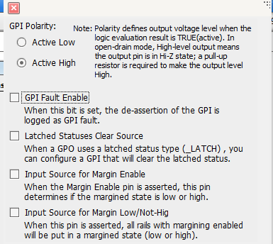
    But what's the use of GPI "special behavior"? What's the diffference between select"GPI Fault Enable" and not select it ?

    By the way, is there any user's guide for Fusion Digital Power Designer (version 2.0.159)

    Thank you.

  • The GPI Fault Enable enables GPI Fault Logging. When GPI is asserted, it is considered a fault and is logged in Flash.

    For detailed information of each feature, please refer to datasheet and UCD90xxx PMBus Command Reference, available on ti.com.

    For a step-by-step guide of Fusion GUI, you may refer to UCD90240 datasheet. There is a section describing how to use the GUI. Most content also apply to UCD90160.
  • GPI Fault Enable/Logging is an option that allows a fault condition, separate from the operating conditions already being monitored by the sequencer, to be logged by the sequencer.  Customer defines what event is associated with the Fault Enable pin changing state.

    Example: Another device on the board has a output pin that toggles when it experiences an internal fault condition, let's say an over temperature event, if that pin is routed to a Fault Enable input pin then the sequencer can log that separate OT event.

    It doesn't need to even be a fault condition, it could be any system action that can assert a pin that the customer wants to know occurred during operation.