This thread has been locked.

If you have a related question, please click the "Ask a related question" button in the top right corner. The newly created question will be automatically linked to this question.

UCD90120A: Brownout functionality of the device and fault logging on UCD90120A?

Part Number: UCD90120A
Other Parts Discussed in Thread: UCD90124A, UCD9090A, UCD90160A

Hi,

I am using a UCD90120A for a new hardware design that I am in process of testing. Are you the right contacts for assistance?

My questions/issues primarily relate to the Brownout functionality of the device and fault logging.


Chip: UCD90120A

Firmware: v2.3.4.0

Using TI Digital Fusion Power Designer v2.0.179 with TI USB Interface Adapter. The TI USB pod and GUI are the only means I am using to communicate with the chip during testing.

My hardware is configured to support Brownout. I have verified that the device is held between 2.9V and 2.6V for >5ms (actual is approx. 9-11 ms).


  1. Is there an errata doc for UCD90120A? I have found  this doc (http://www.ti.com/lit/er/slvz014/slvz014.pdf) which mentions issues somewhat related to what I am experiencing, but am not sure if any/all of the issues apply to UCD90120A.
  2. It seems that when I configure the device with “Enable Brownout Support” box checked/enabled, Brownout functionality does not work (detailed fault logging at shutdown, runtime clock restarts at 0), but when the box is unchecked/disabled, Brownout fault logging, run-time clock saving seem to work expected.
  3. When “Enable Brownout Support” is checked/enabled, Clear Logged Faults does not seem to work as expected – The faults are cleared until a power cycle, but then the exact same detail logged faults return (same time, fault type, and measurement – highly unlikely it is a repeat fault).


I feel like I am missing something obvious here. I am hoping that there are some known issues or common pitfalls that I should be looking for.

Let me know what additional details would be helpful.

Thanks,

David

  • Hi David
    #1. what're the issues that your are experiencing?

    for the #2 and #3, what are the size of hold-up capacitor? do it provide enough current as described in the data sheet?

    Thanks
    Yihe
  • The issues being experienced are summarized in #2 and #3. It really seems like the "Enable Brownout Support" functions the opposite as expected.

    Is >1630uF capacitance, behind a blocking diode as recommended in data sheet. These caps are low ESR.

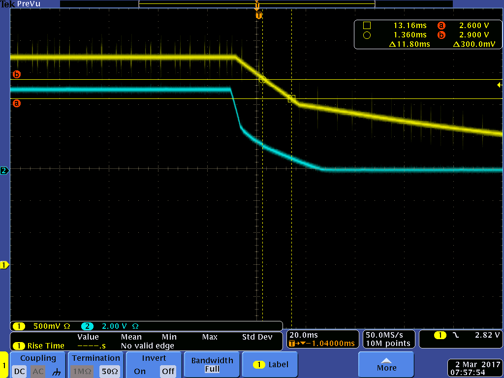
  • Could you please share the project file, schematics related to brownout and a waveform when V33 ramps down for brownout?

    Regards

    Yihe
  • Blue Trace = Prime input power to the board

    Yellow Trace = 3.3V supply to the UCD90120A

  • Under brownout mode, if clear fault log must be issued, please follow below steps:
    1. disable the brownout mode
    2. send out the clear fault log command to clear fault
    3. re-enable the brownout mode.

    otherwise, old faults will be back.
    There are two memory banks inside device for ping-pong buffer logging. there is a counter associated with each memory. the bigger counter indicates a newer infomration.

    When brownout mode is on, there is mis-sync between the counters causing the non-erasing bank treated as newer information to display.

    Regards

    Yihe
  • I was able to clear the logged faults by first disabling brownout mode as you indicated.


    Part of my question still remains: When brownout mode is enabled, the runtime clock starts from 0 every time the device is powered up. I would like the runtime clock to continue counting where it left off to give an estimate for total device powered on time.  (I am observing this through the TI GUI Tool)

    Otherwise the logging functions of brownout feature appear to be working correctly.

    Is there some special programming sequence in order to enable an absolute, runtime clock for the device?

  • If the brownout mode is on and there is enough hold up time, the RTC shall be saved and retrieved after power cycle.
    1. Set RTC
    2. disable brownout
    3. clear fault log
    4. enable bronout
    5. triger any fault
    6. power down
    7. power up
    after above step, did you see correct RTC?
    Regards

    Yihe
  • No. The logged fault and logged fault detail appear as expected, but the RTC (Configre > Global Configuration > Run Time Clock > Device Clock Reading) always resets to zero on power up.

  • if a new fault was triggered, is the fault logged with correct RTC or not? Could you share your data flash dump on the next powr up?

    Regards

    Yihe
  • The logged detail fault has the time of the RTC that the fault occurred (which is during power down). On the subsequent power up, the RTC returns back to zero and counts from zero. I am sending you an email with the flash dump.
  • After some research, this is a known issue of the device, the RTC is reset to 0 on the next power cycle when brownout mode is enable.  This issue is fixed in the UCD90124A, UCD9090A and UCD90160A.

    The workaround is to update the RTC each time UCD is power down.

    Regards

    Yihe

  • Thank you for the input. Unfortunate that it is a problem with the device, but it is good to know the issue is not with my design.
    Is there an errata document that I can reference with this information for UCD90120A?