This thread has been locked.

If you have a related question, please click the "Ask a related question" button in the top right corner. The newly created question will be automatically linked to this question.

UCD9090: UCD Functional Lock during fast power on/off test

Part Number: UCD9090
Other Parts Discussed in Thread: TL431,

We are facing few issues on the UCD power cycle functionality.

When we do external power cycle after some 15mins/30mins of continuous board functionality, we are seeing frequent lock on the UCD. UCD is not sending out EN signals for other regulators. Board power rails are not coming out.

 We captured the waveforms for external 5V, 3.3VS (UCD supply), board power supplies 3.3V & 1.0V (based on enable signal given from UCD).

Here are the observations from the waveform,

1. When doing fast power cycle when the board is under Longer time of operation:

- 5V rail starts to die down. Immediately it sees an increasing in voltage and later started to fall continuously.

- 3.3VS fall and then retain its stable 3.3VS due to the TL431 device on its path. Then, later 5V to die down.

- If we are not giving longer time for 5V fall and turn on again, some time the UCD is in lock condition and not giving out any output. Looks like the UCD is under lock condition.

- After giving sufficient time from then and then power on we could see UCD functioning.


2. When doing fast power cycle when the board is under Longer time of operation:

  • 5V rail starts to die down very sharply and 3.3VS is following it. Even with lesser OFF time duration, when the board gets power, the UCD starts functioning.
  • Even we repeated this for multiple times, we could see proper output.
  • Only when the off time is very shorter, we are seeing the UCD is not functioning. It gets into a lock condition.

 The behavior of power cycle wave for the 5V & 3.3VS is not same between normal operation (lower temp) & at longer operation (higher temp).

 One way we are seeing a different behavior on the 5V rail on these two scenarios.

But, very much interested to see, why the UCD is not regaining its functionality even when 3.3VS is stabilized. Would the temperature be a part of this? or Any fault setting could have happen while the 3.3VS is going down to its recommended value and refused to release this even after 3.3VS regains its normal value?

We already removed the 47uf caps on the 5V to 3.3VS conversion circuitry, based on the input we received from previous threads.

 We would like to have your support on this.

Regards, 
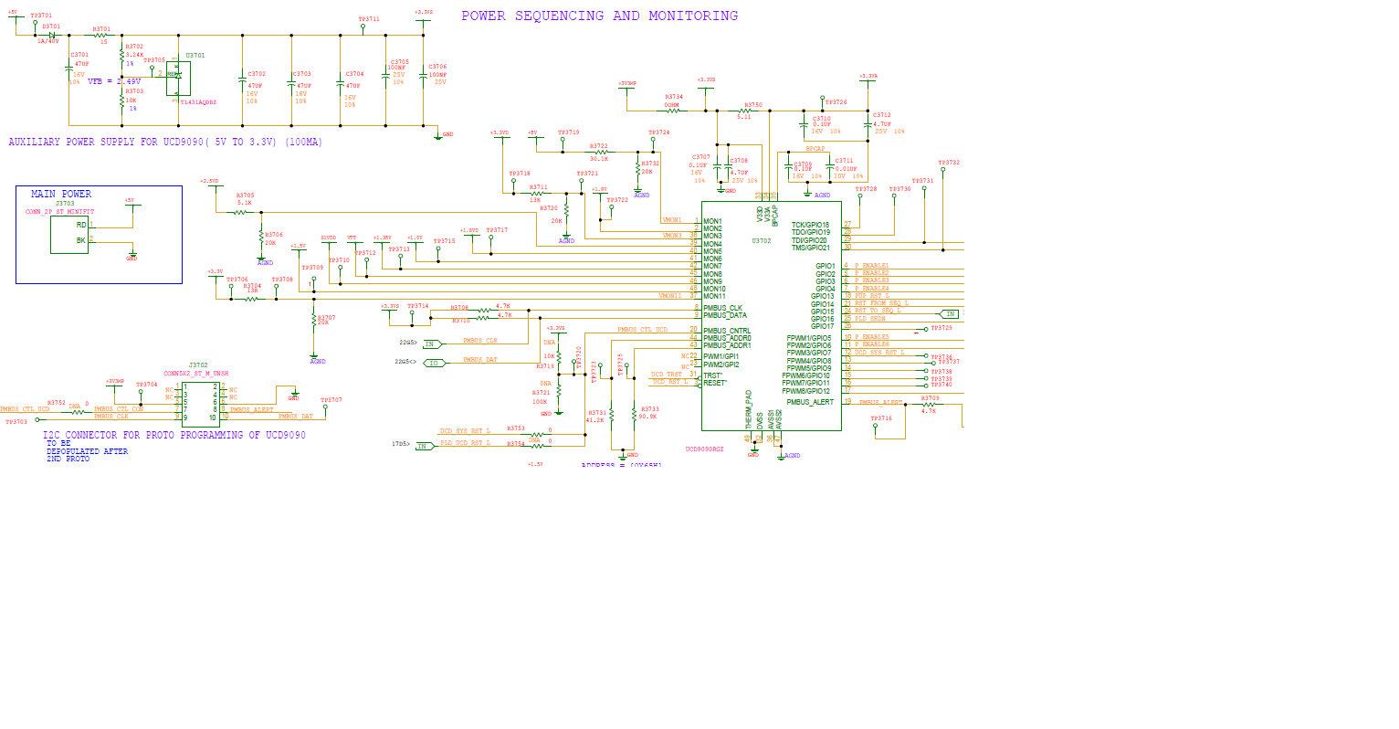
UCD9090_FastPowerOn-Off-Test.zip

Felix.

  • thank you for the waveform. it is very obvious that when the V33VS has a very small dip(down to 3V, it is hard to tell from the waveform), the V33 and V1.0 rails were never back. if the UCD is lock, it shall not communciate via I2C/PMbus. Could you please check communication of UCD?

    Is the brownout feature enabled? From the waveform, it is very hard to tell before the "LOCK", how low is the V33VS? if the V33VS is below 2.9V, device enters the brownout condtion and stay until a POR is met(lock conditon). In your case, i did not see that the drop of V33VS could trigger POR as described in the Data sheet. A dip to 2.9V but not met POR with brownout feature enable may cause device lock.

    If the V33VS is above 2.9V or the borwnout feature is not enable, it could be due to the fault shutdown of 5V/V33VS input. I assume that UCD is monitoring either 5V or V33V rail, when either has a dip causing UNDER_VOLTAGE fault, UCD shutdowns the 3V and 1.0V rail, but since the dip of 3.3V is not low enough to reset the UCD, therefore the dip of V33VS does not cause anything other than the shutdown of 3V and 1.0V. the UCD is still alive and it just shutdown the 3V and 1.0V rails as a protection. Please check your configuration to see whether this theory is met.

    Hope this helps.

    Regards
    Yihe
  • THanks a Lot Yihe. This explanation 

    We have physical connection for I2C/PMBUS communication with processor. But we are not utilizing that. We have programming connector option. Through this we are doing the UCD programming.

    We didn't  enable the Brownout feature on our set up.

    Also, we mornitor 5V, not 3.3VS and set 4.5V as PG & UV limit as well.  Yes, when 5V falls below 4.5V  and 3.3VS stays drops around 2.6V, we could see a complete UCD lock and not powering 3.3V & 1.0V.  We felt this could be due to 5V UV fault setting. Only when we allow the 3.3VS fall below 2.4V (as per UCD datasheet reset), its sees a POR and starts functioning on next power up and giving out proper EN lines. Otherwise, UCD keeps it under reset.  

    Then we removed 5V monitoring from the image file and had the board regulator rails alone. Even now, we see UCD lock on faster switch on/off main power rail(5V). 5V drops around 4.5V and UCD supply drops down to sometime 2.6V, some time 3.0V level and with some negligible dip too. In this case, the measured OFF time comes around 16msec. But the 5V and 3.3VS regains its normal values. Only on another power cycle when the POR happens UCD lock got removed.

    Kindly confirm whether even without 3.3VS (UCD supply) monitoring, whether the UV fault sets for these rails and will make the UCD lock?

    In this case, could you please suggest what kind of work around to bring the 3.3VS dip to POR level faster enough in smaller OFF time?

    Regards,

    Felix.

  • Please confirm when UCD is claimed "lock", were you still able to communciate the device via I2C?
    Thanks
    Yihe
  • This issue was closed now after local support. During the power cyle test, there was dips on other buck converter monitored byUCD9090. The dip caused a configured fault response to turn off the rails. UCD is functioning as expected.

    Regards

    Yihe

  • We found the UCD supply 3.3VS which is derived from 5V, was not falling to POR Level (2.64V). At the same time 5V powered the other two regulators saw a huge dip during the power shutdown as it was not meeting the min requirement of the regulator 4.5V.
    Atlast, we resolved this by adding a supervisory reset IC for the 5V rail and the reset signal of the supervisory IC is connected to the UCD reset pin. This way when we see a 4.64V drop on the 5V rail, supervisory IC send out a RESET signal to the UCD reset and that resets the UCD and did power cycle.
    Thanks for the support on closing this.
    Regards,
    Felix.