This thread has been locked.

If you have a related question, please click the "Ask a related question" button in the top right corner. The newly created question will be automatically linked to this question.

TPS2592

Other Parts Discussed in Thread: TPS2592AA

Hi,

Intend to use TPS2592AA for Safe Startup of Brushless DC Fan (reference App Note attached) .The reference design shown is for a Fan with higher current requirement.How to I simulate to find out component values for my specific requirement.

Webench only offers simulation for capacitive load and the fan is inductive load so I can't use webench.Fan datasheet is also attached.PMD1204PQBX-A2F.GN.pdfTPS2592AA-APP NOTE-DC BRUSHLESS SAFE START UP.pdf

  • Hello Pallavi,
    You can refer to the TPS2592A data sheet and a design calculator to achieve the specific design requirements.
    Alternatively, you can send us your design requirements along with fan data sheet, we will suggest you the parts values around TPS2592A to meet your design specifications.

    Regards
    Dinesh
  • Hi Dinesh,

    Thanks for your reply.
    Application : Safe Startup of Brushless DC Fan
    Fan Datasheet : Attached with Query PMD1204PQBX-A2F.GN.pdf
    We are looking at an VIN of 12V (5% tolerance)
    12V VIN will always be ON hence we want to make the Fan Hot Swappable with TPS2592AA?

  • Hello Pallavi,

    Thanks for the information.

    The rated current of your fan is 0.58A, so I would suggest you to set the current limit  about 25% higher.

     so for the 0.75A worst case start up current you would need RILM resistor 6.8k.

    Please Note the accuracy of the current limit will be > 30% for such lower current, But still I  do not see any problem for your safe start up of your fan.

     You can run this at 12V input.

     Please let me know for the further question.

     Regards

    Dinesh

  • TPS2592 Eval board.pdfHi Dinesh,

    Thanks.

    Please let me know the suggested Capacitors and Diode for the circuitry.Presently we are referring the Design shown in TPS2592 Eval board.It is attached for your reference.

    Regards

    Pallavi

  • Hello Pallavi,
    Please use other values as mentioned in Figure 6. Typical Circuit Diagram with TPS2592A for Safe Start-Up of Fan of the application report.
    you do not need anything else to run the fan.
    Regards
    Dinesh
  • Hi Dinesh,

    Did you use following formula for Rlim calculation?

    Rlim = (Ilim-0.7)/(3x10^-5) as given on Pg 19 of datasheet.

    Using this formula and Ilim 0f 30% more than the requirement i.e 0.75 Amps I am getting Rlim of 1.67K..Please clarify

    Please also let me know the maximum current requirement of TPS2592 in our case.

    Thanks

    Pallavi

  • Hello Pallavi,

     Since your Fan  current is very low and in this lower range the current limit accuracy is wide.

     if you see the Figure 31. Accuracy vs Overload Current Limit In the data sheet , you will see we do not recommend the such low value.

     Please use following calculator  http://www.ti.com/product/TPS2592AA/toolssoftware to get the best RILIM value.

     I have used Imax = 0.75 and that gave me RLIM=6.67k.

    Regards

    Dinesh.


  • HI Dinesh,

    Guess you are referring to the Excel sheet calculator here.

    Request you to share the excel where 6.67K value is coming.I am not getting this value so want to confirm.

    Appreciate your quick responses.

    Thanks

    Pallavi

  • Hello Pallavi,

     Attached is the calculator used for your design.

    Regards

    Dinesh

    TPS2592-Design-Calculator-RevA2.xlsx

  • Thanks Dinesh,

    This should do it..Will get back incase anything else is required.
    Appreciate the timely response.

    Regards
    Pallavi
  • Hi,

    Please find attached the final design (Snap1) and Excel Sheet Calculator for Descrete requirements (TPS2592-Design-Calculator-RevA2) following our discussions earlier.

     6303.TPS2592-Design-Calculator-RevA2.xlsx

    Kindly suggest on the following:

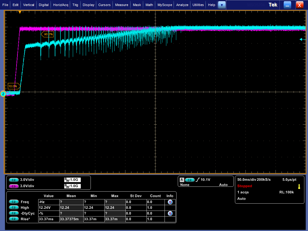
    1) Attached is a snapshot of Vin and Vout wrt TPS2592. (Snap2)

    We find a Vout Ramp up time of 250+ ms however the Tchg_dVdT as in excel is 12.03 ms.

    Is there any way of calculating the Vout settling time?

    Is it only dependent on Cdv/dt value or is it dependent on any other parameters too?

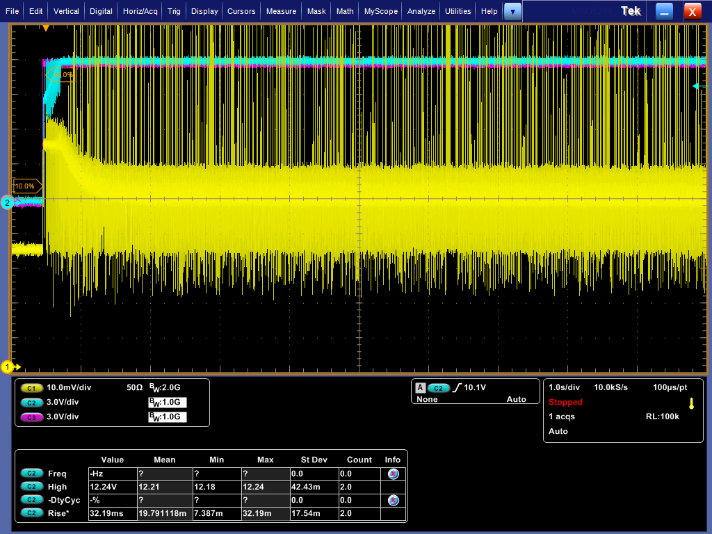
    2)Attached is Snap3 of Vin,Vout and Iout.As clearly seen the I out spikes reach beyond the Ilimit of .9Amps set in excel sheet.

    Why is that?

    Please suggest how to limit it as required.

    3) TPS2592AA App Note "Safe Startup of Brushless DC Fan with TPS2592A eFuse" (attached for reference) Pg 6 mentions "Since the fan start-up current is limited to 2.5 A, the time fan takes to achieve the final speed and settling current is larger (≈1200 ms) as expected." Please explain how this value of 1200ms was calculated.The Excel Sheet calculator does not give this value with t

    he given parameters.3250.TPS2592AA-APP NOTE-DC BRUSHLESS SAFE START UP.pdf

    4) As per the descrete values of Fig6 in the App note the En/UVLO on range is from 9.09V to 10.4V (based on the resistor divider).

    however the TPS2592 DS mentions that operating range is limited to 6V.Please explain.

    Also the leakague current in this case will be 160uswhile it should be limited to 20us as per DS.

  • Hi pallavi s,

    I'm going to move this thread to the appropriate forum.

    -Aramis
  • Hi Pallavi,

    1) We find a Vout Ramp up time of 250+ ms however the Tchg_dVdT as in excel is 12.03 ms. Is there any way of calculating the Vout settling time? Is it only dependent on Cdv/dt value or is it dependent on any other parameters too?

    1A) Tchg_dVdT calculations hold true only for capacitive loads. The motor demands heavy current until back EMF is developed. So, here, the device is in current limit mode during startup.

    2)Attached is Snap3 of Vin,Vout and Iout.As clearly seen the I out spikes reach beyond the Ilimit of .9Amps set in excel sheet.
    2A) can you please let us know how you measured Iout? Is it through current probe or voltage across sense resistor? your waveform looks lot of nice pickup with 10mv/div scale.

    3A) 1200ms is the measured value.

    4A) 9.09V to 10.4V refers to Vin range where as 6V refers to max. voltage that can be applied at En/UVLO pin.
    similarly 160us is the shunt current from Vin to GNd through resistor divider network, where as 20us in DS mentions the leakage current into En/UVLO pin.

    Regards,
    Rakesh