This thread has been locked.

If you have a related question, please click the "Ask a related question" button in the top right corner. The newly created question will be automatically linked to this question.

TPS22959: I want the data of TPS22959

Part Number: TPS22959
Other Parts Discussed in Thread: TPS22990

Hi,

Please let me know  about TPS22959 .

Q1.Our customer would like to know the graph data of "Ron vs Iout like a Figure 12 at VIN=3.3V,VBAIS=3.3V".

If you have the information, could you please send to me?

Q2.Our customer would like to know Iout at Figure32 to 39.

I guess that there is RL=10Ω , so Iout is "Vout/RL".

Is my understanding correct?

If No, could you please let me know Iout.

Q3.Our customor would like to know the data of Switching Characteristics at VIN=3.3V,VBAIS=3.3V and Iout=7A.

If you have the information, could you please send to me ?


Best Regards,

Yuto Sakai

  • Hi Yuto,

    We do not have any of this data for the TPS22959 already collected. If it is needed, then I can go into the lab and collect it. However, have you taken a look at the TPS22990 device?

    The TPS22990 is a 10A device with an on-resistance of 3.9mΩ at VIN=VBIAS=3.3V (lower than the 4.4mΩ on-resistance of the TPS22959). It also comes in a smaller 2mm x 3mm package and includes a power good signal as well as an adjustable rise time.

    Q1. Output current does not directly affect the on-resistance of the device, it is the self heating caused by the current which changes the on-resistance. For more information on this, please take a look at sections 3.1 and 3.2 in the following app note: .

    Because of this, it is better to look at the way on-resistance varies across temperature to see how the device will behave at 7A.

    Q2. Yes, your understanding is correct, the timing is taken with a 10Ω load and the resulting load current is VOUT/RLOAD.

    Q3. As mentioned, I do not have this data on hand. In general, a higher load current will usually make the delay time and rise time longer. The fall time and turn off time will be faster than in the datasheet because the load is stronger and it will pull down the output voltage faster.

    The TPS22990 already has data at VIN=VBIAS=3.3V and is able to support the required 7A load. It also has an adjustable rise time so if you are worried about turn on timing then you can change it to whatever is needed. Do you think this device could work for your application?

    Thanks,

    Alek Kaknevicius

  • Hi Alek-san,


    Thank you for your kind reply.


    I will try to propose TPS22990 to our customer.


    However, I'd like to ask if you could take the data for the TPS22959 of "Iout vs RDS at VIN=VBIAS=3.3V",and "switching characteristics at VIN=VBIAS=3.3V and Iout=7A".


    I kindly ask for your cooperation.


    Best Regards,

    Yuto Sakai

  • Hi Sakai-san,

    The "Iout vs RDS" graph for VBIAS=VIN=5V and VBIAS=VIN=2.5V are less than 0.5mΩ apart, and the VBIAS=VIN=3.3V curve would fall in between them. Is this <0.5mΩ range not accurate enough for the customer?

    As for the timing data, I can measure this by early next week. Is this acceptable?

    Thanks,

    Alek Kaknevicius

  • Hi Alek-san,

    I will propose to the customer.
    There is no ploblem measuring the timing data by early next week.

    Thank you for your kind support.

    Best Regards,
    Yuto Sakai
  • Hi Sakai-san,

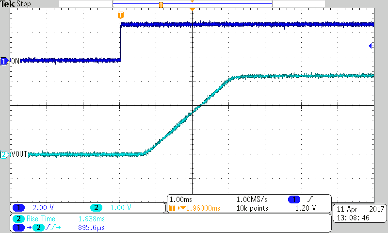
    Please find the scope shot below showing the turn on behavior for VIN=VBIAS=3.3V and IOUT=7A.

    The rise time was measured as 1.838ms and the delay time was 896us. Please let me know if you need any additional information.

    Thanks,

    Alek Kaknevicius

  • Hi Alek-san,

    Thank you for your kind support.

    Could you let me know the TEST CONDITION ,RL and CL?

    And it would be wonderful if you could take the data of the turn off behavior for VIN=VBIAS=3.3V and IOUT=7A like Figure 36~39.

    Best Regards,

    Yuto Sakai

  • Hi Sakai-san,

    The load was created using a resistance which drew 7A from the power supply when the switch was turned on, and the capacitive load was 0.1uF.

    The turn off behavior is dependent on how quickly the load discharges the output capacitance. For an output capacitance of 0.1uF and a load resistance of about 0.47ohms, the fall time would be about 0.1us. This of course will vary depending on the load attached. Does the customer have a specific requirement here?

    Thanks,

    Alek Kaknevicius

  • Hi Alek-san,

    Thank you for your kind reply.

    For customers, I think that information is sufficient.

    Thanks,

    Yuto Sakai