This thread has been locked.

If you have a related question, please click the "Ask a related question" button in the top right corner. The newly created question will be automatically linked to this question.

TPS22810: Adding reverse input protection

Part Number: TPS22810
Other Parts Discussed in Thread: TPS2660

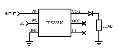
I have designed the TPS22810 into a circuit as a topside power switch. I believe I did not account for the possibility of my input being connected in reverse, though, and so I am trying to adjust my design accordingly.

The circuit does not make use of the QOD or CT pins. A microcontroller controls the enable signal. The load that the switch controls is already protected from reverse currents. It looks as follows in the system:

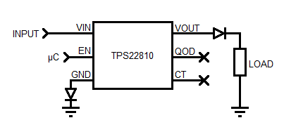
The input can go up to 17 V, and has the potential to be connected backwards for -17 V at the input. I would like to avoid putting a schottky diode inline with the input, since I really do want to avoid the additional losses. I have seen some parts that allow you to add reverse protection by putting a diode on the low side, and I was wondering if that would be sufficient for this part as well, especially in light of the fact that I don't get any reverse current from my load. What I'm proposing is this:

The diode on GND could be made a Schottky if necessary.

If an inline diode or MOSFET would be the only way to add reverse input protection to this part, I could use a suggestion of an alternate part that already includes the reverse protection. I'm extremely space limited, though, which is one reason I selected this part in the first place.

  • Hi MR Flashlight,

    Technically, adding a diode in the ground path could protect against reverse polarity, but it would also be recommended to add a resistor in series to limit the current (~1k should do the trick). Schottkey is preferred since the voltage would be clamped to a lower value. Also, the VIH level of the device would increase due to the shift in device ground.

    In general though, the reverse polarity could not be sustained for lifetime conditions, only brief moments of time. It is difficult to classify this since we haven't done any extensive testing with this configuration. 

    The only integrated power switch we have with reverse polarity protection is the TPS2660, but this may be overkill for your application.

    Also, can you describe your application? We do not get this request often and would like to understand where it is coming from.

    Thanks,

    Alek Kaknevicius

  • The TPS2660 would be way too large for my application.

    I design flashlights. This particular product has the battery separated from the light source, and it would be possible to plug the two together backwards. It wouldn't work in this configuration, so I don't imagine it would be left like that for longer than a few minutes at a time. Size and efficiency are key, so I've been trying to identify the best way to add the protection I need within my space constraints and without losing too much power.

    This solution of putting a Schottky on the ground pin adds 1 or 2 0402 parts without dropping voltage along my power path, which is why I like it. A reverse protection MOSFET would be about twice as big in terms of components added, and also would add a small drop. A reverse protection Schottky I can fit as currently designed, but it would result in a significant loss of power.

    Would there be any good way of testing out this solution besides buying the part, breadboarding it out and trying to see if it works? I'm not sure if any Spice models would be complete enough to see how the part behaves outside of spec.
  • I wanted to provide an update.

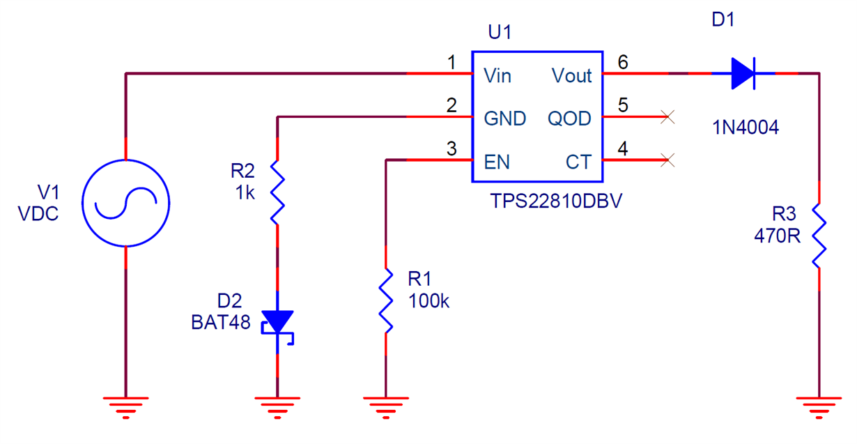
    I purchased the TPS22810 in the SOT23-6 package. I then breadboarded out the following circuit, putting the TPS22810 on a breakout board.

    I applied 5, 10, and 17 V in both forward and reverse configurations. In the forward configuration, I verified that jumping the enable pin to Vin turned the output on and off. In the reverse configuration, I let the circuit sit for over an hour while watching for failures (such as current flow), then switched back to forward to verify operation. All of my tests passed.

    I'm comfortable enough with this to move forward with it in my solution. Obviously, to properly verify that this works, the original silicon design would need to be consulted, or this test would need to be executed on hundreds to thousands of units, but for my purposes I am content right now that this will be sufficient.

  • Hi MR Flashlight,

    Thank you for the update, and glad to hear that the circuit is performing to your expectations! I will keep you updated with any further investigation our team does on this configuration.

    Thanks,

    Alek Kaknevicius