This thread has been locked.

If you have a related question, please click the "Ask a related question" button in the top right corner. The newly created question will be automatically linked to this question.

TPS25940: TPS25940 passes current in the opposite direction

Part Number: TPS25940

Hello. Sorry I bad know English.

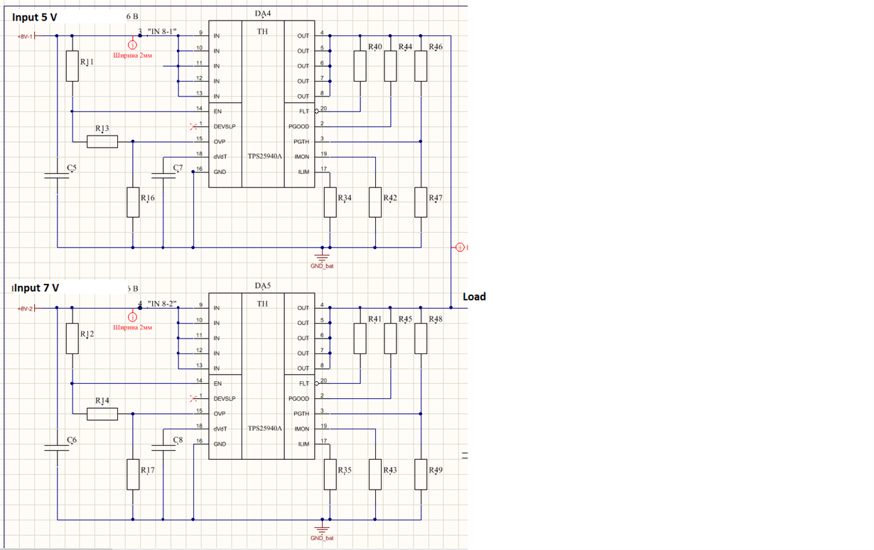
The problem is as follows: connected in parallel TPS25940 from different sources 5 and 7 volts on one load. When disconnected from TPS25940 a single power supply, input TPS25940 appears the voltage of the second power source. Tell me what could be the problem?

На русском языке.

Простите я плохо знаю английский.

Проблема заключается в следующем: подключил параллельно TPS25940 от разных источников 5 и 7 вольт на одну нагрузку. При отключении  от TPS25940  одного источника питания,  на входе TPS25940  появляется напряжение второго источника питания. Подскажите в чем может быть проблема?

  • Hi Maksim,

    Reverse current blocking becomes functional after detecting reverse voltage of 10mV (typ) across the device. When the VOUT is raised above IN, there will be spiky small reverse current from VOUT to IN. The spiky small reverse current should generate 10mV reverse voltage to activate reverse current protection. If VOUT raises very slowly, there will not be enough magnitude of reverse current to cause 10mV drop and hence fails to detect and cutoff.

    Can you please provide information of your system operation to solve this
    when both 5V, 7V are available, Do you want always the higher voltage source (7V) to power the load ?
    what is the source for 5V ? DC/DC converter or battery ?
    what are the values of C5 and C6

    Best Regards,
    Rakesh
  • В случае если сначала на 1 подключить 5 вольт после на второй подать 7 вольт напряжение на первом тоже поднимется до 7 вольт, если подключить сначала на второй 7 вольт, а после на первый  5 вольт напряжение на первом не изменится.

    при отключении второго 7 вольт (когда на первом 5 вольт) напряжение на втором опустится до 5 вольт. 

    Необходимо чтобы эти микросхемы выполняли роль идеального диода (защита одной батареи от перезаряда от другой)

    ток нагрузки на первый и второй составляет до 0,5 ампера.

    5 и 7 вольт берутся от разных батарей (АКБ)

    Емкость С5 = С6 = 0,1мкф

    Емкость С7= С8 = 1,5нФ

    На русском языке.

    Простите я плохо знаю английский.

    If on 1 is connected 5V and after on 2 is connected 7V, then voltage on 1 raise to 7 V. If on 2 is connected 7V and after on 1 is connected 5V, then voltage on 1 don`t change. If on 2 disable 7V (when on 1 is 5V) voltage is drop to 5V. This chip must do role ideal diod (protection of one battery against the possibility charge from other battery). Current load is 0.5A. Voltage 5V and 7V take from different battery. Capacity C5 = C6 = 0.1 microF. Capacity C7 = C8 = 1.5 nF.

  • Hi Maksim,

    Thanks for the details.

    unfortunately, this chip is not replacement for a ideal diode. As explained, this chip needs small reverse current to detect and cut-off the path.

    The below modification will help address your issue. Please implement output overvotlage cut-off  for 5V eFuse as shown below. you can chose R13 and R16 values to cut-off at 5.3V (typ). 

    Best Regards

    Rakesh

  • Thank you for help