


Hi Team,
In the application schematic in the datasheet, there is a resistor and capacitor connected to the CS pin, which connects to an MCU.

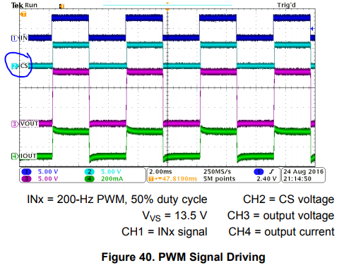
The resistor and capacitor are not labeled and there are no recommended values. I would like to obtain the same square waveform as the diagram shown below, but the R and C values create a filter, which can then change the output to a sawtooth type waveform instead of a square wave. Which values of R and C were chosen in the diagram above to still allow the MCU to see the square wave as shown below for CS?
Thank you!
Jared
