This thread has been locked.

If you have a related question, please click the "Ask a related question" button in the top right corner. The newly created question will be automatically linked to this question.

BQ51013B circuit not working

Other Parts Discussed in Thread: BQ51013B, BQ51013

Hi,

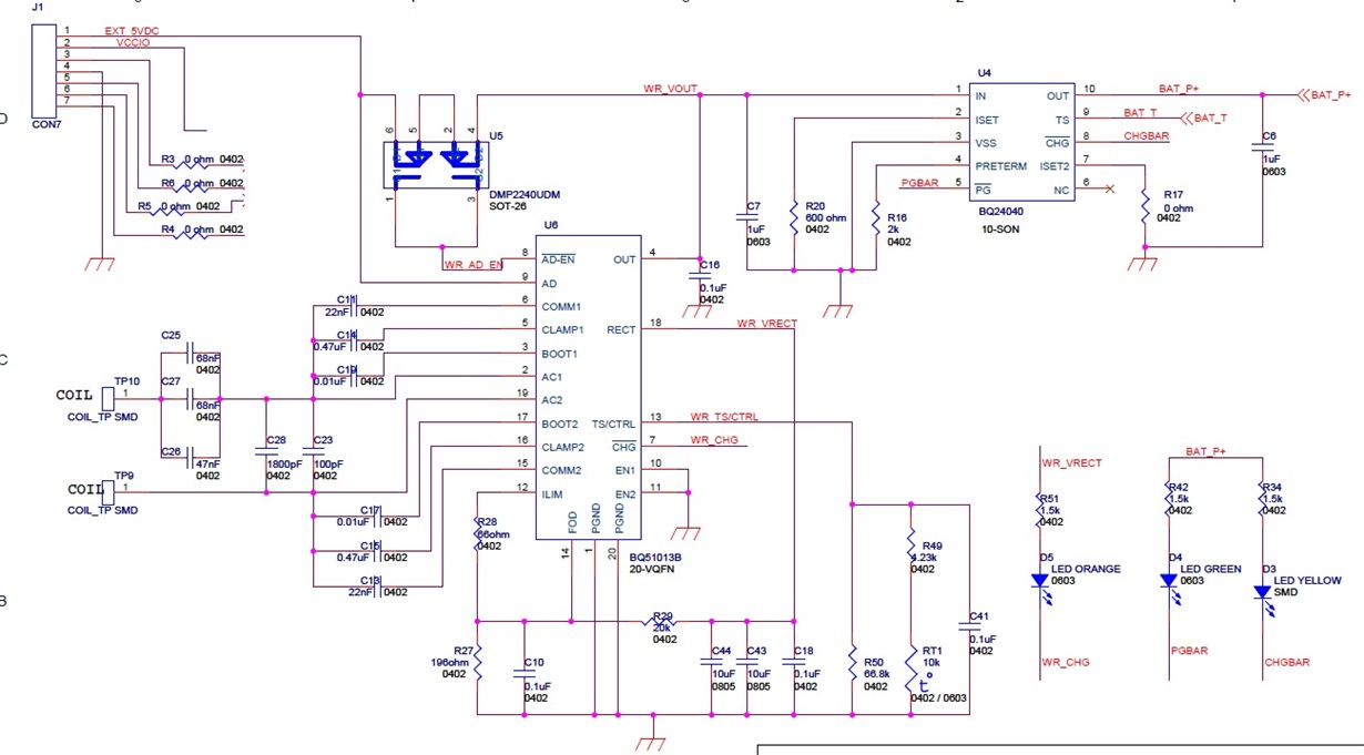
I am using BQ51013B in one of my designs for charging a lithium ion battery. The circuit is as shown.

The circuit works in wired charging mode. When I give a 5V dc at the connector J1 it works and battery is getting charged.

But the wireless charging is not working. There is no output voltage in the wireless charging mode. The design uses receiver coil IWAS4832FFEB9R7J50

(I have used a Qi compliant wireless charging pad bought from amazon)

Please help.

  • Varun,

    There are a couple of things that I see that will have an impact on the system.  The "Cs" capacitors (C25, C26 and C27) are shown to be 0402 capacitors.  These set the resonant frequency of the system and will pass all of the current from the coil to the bq51013B.  These should be at least 0603 and should be X7R.  They should also me a minimum of 25V capacitors.  Based on R28 + R27, your system is set for 1A as the expected current level.  Especially at that current level, the capacitors should be 0-603.  The other capacitors touching AC1 and AC2 should be sized larger as well.  

    The Cs value should be chosen based on the Ls and Ls' of the coil.  The coil mentioned above is 9.7uH for the Ls.  Have you measured Ls'?  As a first pass, I think the total capacitance at Cs is a low.  Being low will impact efficiency and possibly functionality, but is probably not the main problem here.

    For troubleshooting, I suggest you start by looking at the RECT signal.  RECT shows the rectified voltage from the AC1/AC2 lines.  See figure 17 in the bq51013B datasheet for a good startup signal.  If RECT is not moving, the power from the AC1/AC2 lines is not getting to the device.

    It might also be a good idea to set the resistance on the TS/CTRL pin to a known 10k ohms to ensure there are no issues with the NTC.

    Regards,

    Dick

  • Hello,

    This is Balaji.  Currently I am working on TQ51013B wireless power receiver.  I wanna know how to calculate the value of capacitor that is at COMM1, COMM2, CLAMP1, CLAMP2, BOOT1, BOOT2,.  Is there any formulae to calculate those values?  Thanks in advance.

  • In the datasheet TI recommends the values of CLAMP and BOOT capacitors as 0.47uF and 10nF respectively. COMM capacitor is used for communicating with the primary coil  through backscatter. The value for the COMM capacitor is taken from the evaluation module for bq51013 (bq51013xEVM-764 Evaluation Module) as 22nF. They have not explicitly specified a formula for calculation of these capacitors. They recommend to use the values used in the evaluation board. Designing these capacitors may require more insight into the communication schemes and protocols and the circuit implementation of the bq51013.

  • Thank you very much.  Your response helped me in many ways. ;)