Other Parts Discussed in Thread: TIDA-00318
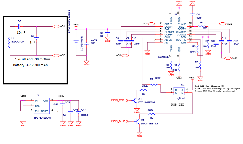
I am using a SAMSUNG wireless charger (Model: EP: PG9201) Transmitter for my project, and at the receiver end I have RX coil of 26uH inductance and 520 mOhm DC Resistance, when i place the reciver assembly on top of the transmitter the coil is picking up voltage and pinging is taking place but it seems like the transmitter is not detecting the device.
based on the calculations in page 29 of the BQ51050 manual the C1 and C2 was determined and as 30 nF and 1nF and when the receiver configuration was placed on the Qi Samsung wireless charger it did not seem to work as intended so started to analyze the circuit i tried to change the C10 & C14, COMM1 & COMM2 cap to 47nf yet did not get any results
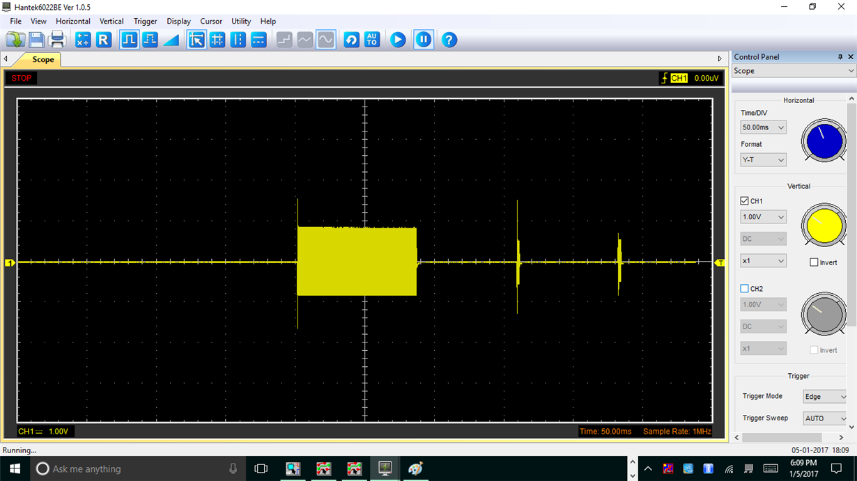
After hooking up the scope across C7 cap I get this in my scope and the frequency out of dual resonant circuit across the Cd (C7 cap) to be 37 kHz where it was suppose to be 1MHz and in the scope !
in the above image i presume the long pulse to be the pinging form the transmitter but the short pulse is it the response packet from the BQ ?
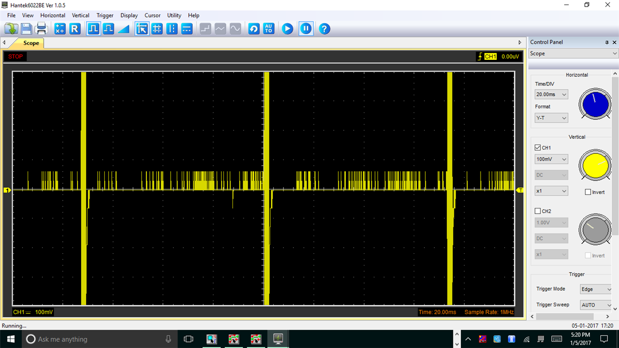
and this seems to continue but the charging does not start.
and this is a more closer view of the wave form. with a voltage of 1.8 V peak.
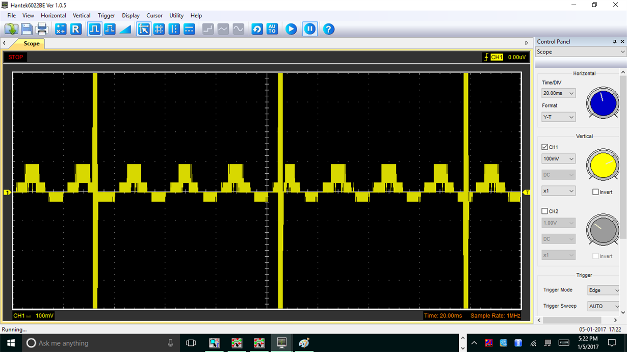
and the next image is when the system without the battery connected
I would like to know what this wave forms are and is there any way for me to analyse what is going on with the BQ15050B or is there any shortcoming in my design, if possible please send me a reference of how the communication wave form looks like between the transmitter and the receiver.


