

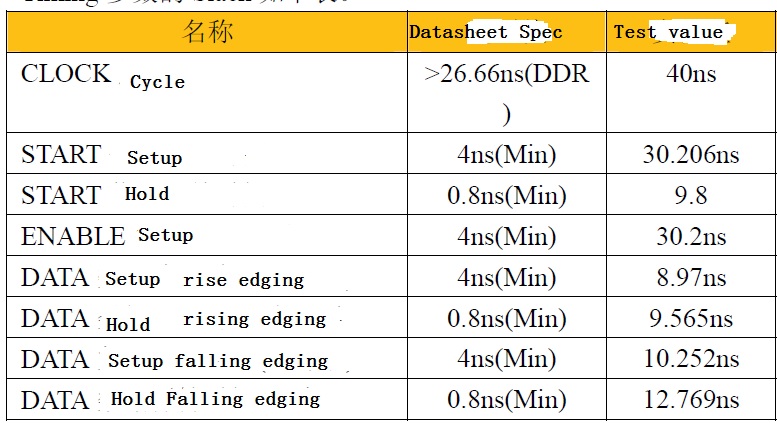
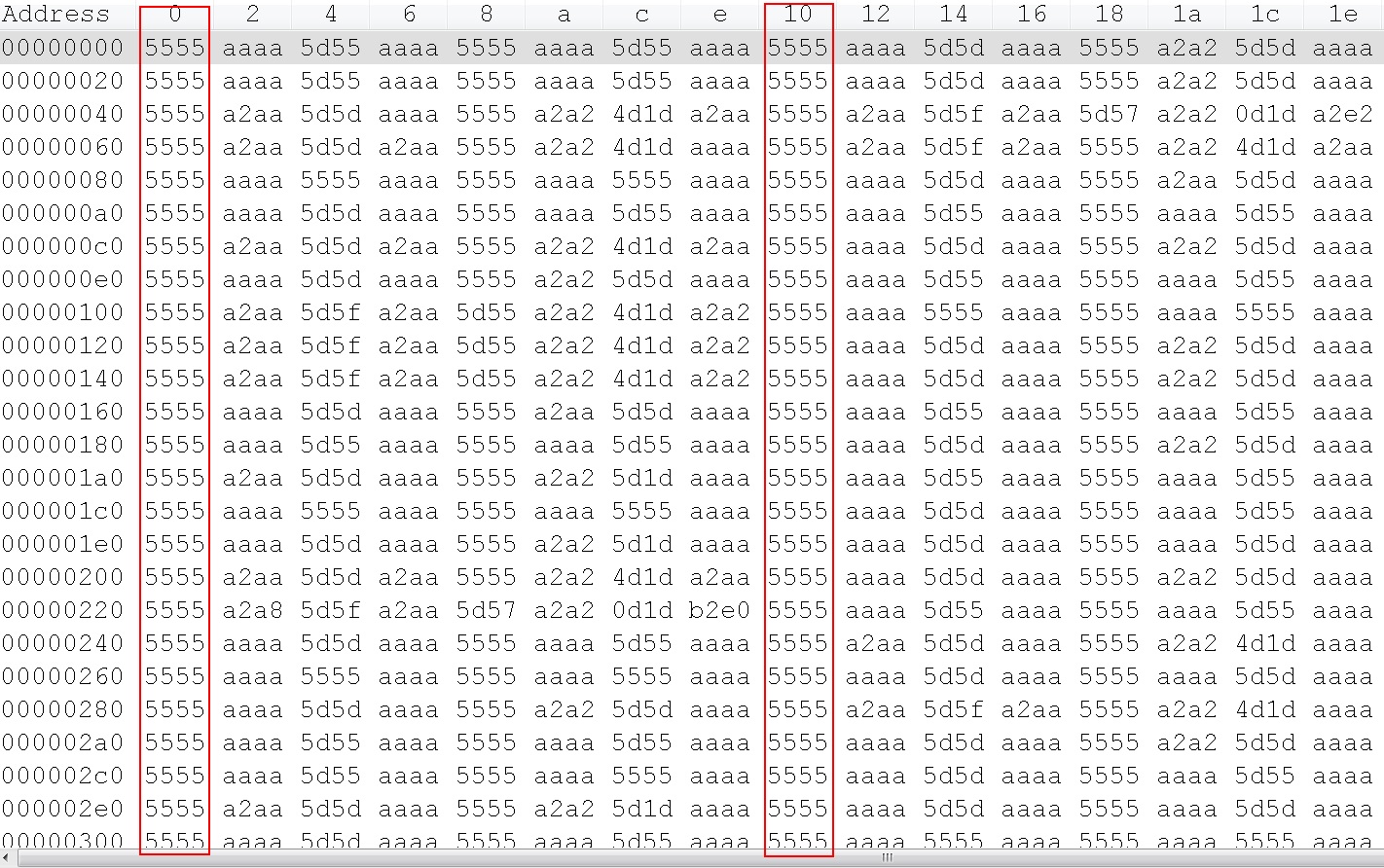
Customer used uPP DDR receive mode, there are some stability issue on few boards after MP, change the data line serial resistor from 20ohm to 50ohm, the error rate decreased, so customer ask the real IO impedance?

-
Ask a related question
What is a related question?A related question is a question created from another question. When the related question is created, it will be automatically linked to the original question.


