This thread has been locked.

If you have a related question, please click the "Ask a related question" button in the top right corner. The newly created question will be automatically linked to this question.

RTOS/TDA2P-ACD: AR0220 Sensor Interfacing to Custom TDA2Px Board

Part Number: TDA2P-ACD
Other Parts Discussed in Thread: SYSBIOS

Tool/software: TI-RTOS

Hello All,

We have previously brought up the AR0220 sensor with UB953/UB954 SERDES on TDA2Px-EVM.

But in our current proto board based on TDA2Px we do not have SERDES. AR0220 sensor is directly interfaced to the CSI2 lines of TDA2P.

So for this to work, how do I bypass my SERDES configurations in the Vision SDK code. Can anyone suggest what changes are required to bypass the SERDES and in what files .

Thanks,

Abhay

  • Abhay,

    Not related to this question, but where do you connect AR0220 sensor on TDA2Px EVM?

    If you are using VSDK 3.3 release, then SERDES is configured in the sensor driver itself, so you need to remove it from your AR0220 sensor driver.

    Regards,
    Brijesh
  • Hi Brijesh,

    While using TDA2Px-EVM, we had connected UB954-EVM to TDA2Px-EVM by removing Sensor Fusion board. And AR0220 sensor was connected to UB954-EVM.

    For Custom board, I have removed the SerDes configurations from my sensor file "apps\src\rtos\iss\src\sensor\ar0220\iss_sensor_ar0220.c".
    Also I have made following changes in file "\apps\src\rtos\iss\src\sensor\iss_sensor_tda2px.c",
    {SENSOR_AR0220, NULL, 0, NULL, 0, BSPUTILS_FPDCAMPOWERLEVEL_OFF, 0U} in the structure "const static IssUtils_Ub96xSerDesCfg gSensorSerDesInfo[]".

    Please suggest whether these changes are correct and do I need any other changes as well.

    Thanks,
    Abhay
  • Abhay,

    Yes, that should be sufficient.
    I meant when you remove SERDES combo, where do you connect this sensor?

    Regards,
    Brijesh
  • Hi Brijesh,

    When SERDES is removed, we connect the sensor directly to the CSI2 lanes of TDA2P.
    Currently we are not able to get any video on HDMI though with the ISS single capture usecase. I will check the sensor configurations again and let you the status.
    Meanwhile, if you can think of anything that needs to be taken care of while using camera sensor with custom TDA2p board, do let us know.

    Regards,
    Abhay
  • Abhay,

    You mean you did some blue wiring to connect this high speed lines?? it is not recommended..

    Rgds,
    Brijesh
  • Hi Brijesh,

    No we haven't done any blue wiring at all. We have received the proper setup for custom TDA2P board and AR0220 sensor from our client.

    Regards,
    Abhay
  • Hi Brijesh,

    We did following experiments with our custom board and AR0220 sensor board interfaced to TDA2P,

    1. We probed the AR0220 sensor using "Bsp_deviceI2cProbeDevice()" API and it was successful
    2. We wrote all the sensor registers and read it back to confirm whether the values are being written successfully.

    But we are still not able to get any new data in the ISS capture link (we are using "iss_capture_isp_simcop_display" usecase).
    After debugging I found that the code is blocked at the function "\links_fw\src\rtos\links_ipu\iss_capture\issCaptureLink_tsk.c" at line "Utils_tskRecvMsg()". It is waiting for the event.
    Can you suggest how do we solve this issue.

    Regards,
    Abhay
  • Hi Brijesh,

    Do you have any update for us.
    Is there any buffer in the driver of camera sensor that we can read to verify that data is coming from CSI.

    Thanks,
    Abhay
  • Abhay,

    Did you check the lane ordering and polarity is correct? could you please first check it?

    Regards,
    Brijesh
  • Hi Brijesh,

    We have done following code changes,

    {SENSOR_AR0220,

           {

    4u, /* I2C Instance id for the sensor */

    {0x10}, /* I2C Address of the sensor */

    {0x10}, /* I2C Address of the serializer (As there is no SER, giving the address of sensor) */

    FALSE, /* Flag for single/multi channel sensor config */

    SYSTEM_VIFW_4LANES, /* Interface width */

    SYSTEM_VIFM_SCH_CSI2, /* Video Interface mode - Single channel capture via CSI2 interface */

              SYSTEM_CSI2_RAW12, /* Input CSI2 Data Format */

    0, /* Virtual Channel Id */

              0, /* Is CSI Enable Required in UB954 */

               {TRUE /* isCplxCfgValid */,

                    {{FALSE, 1}, /* Clock Lane */

                        {FALSE, 2}, /* data1Lane */

                        {FALSE, 3}, /* data2Lane */

                        {FALSE, 4}, /* data3Lane*/

                        {FALSE, 5}},/* data4Lane */

              400 /* csi2PhyClk */ },

    FVID2_VID_SENSOR_AR0220_DRV,  /* sensorDrvId */
    FALSE,     /* sensorBroadcast */
    FALSE    /* enableFsin */

    }

    }

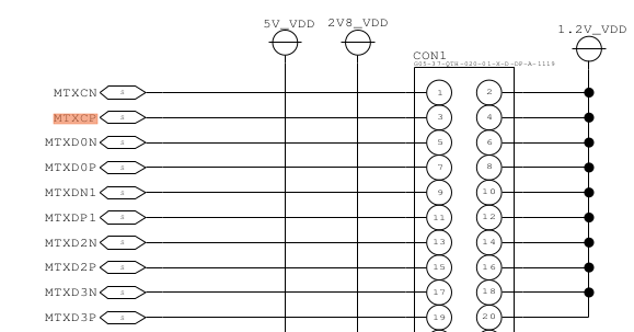
    In our schematic the lane ordering is as shown below. Please confirm we are doing correct changes in the code,

    Regards,

    Abhay

  • Abhay,

    You are using clock lane on lane0, can you please check if this is correct from AR0220 sensor?
    This schematic does not tell where is the clock lane..

    Rgds,
    Brijesh
  • Hi Brijesh,

    This is the connector from which data lanes are connected between the TDA2P and AR0220 sensor,

    Pins 1 & 3 are clock lines. Can you please verify if clock lanes and polarity is fine. This looks OK to me.

    Regards,

    Abhay

  • Hi Brijesh,

    We even probed the CSI2 lines on oscilloscope and we got the signals. But still are ISS chain is not working .

    Regards,
    Abhay
  • Abhay,

    Can you provide dump of below registers?
    0x489B 0350
    0x489B 0304

    I am assuming that you are using PHY0 to connect the sensor.

    Rgds,
    Brijesh
  • Hi Brijesh,

    Please find below the Register values observed in CCS memory browser,
    0x489B 0350 = 0x00000000
    0x489B 0304 = 0x4A054321

    Regards,
    Abhay
  • Abhay,

    Reset Done itself is not getting detected.
    Can you please check the CSI clock of AR0220 sensor and configure DDR clock in CAL accordingly?

    Regards,
    Brijesh
  • Hi Brijesh,

    We also check the register value of CM_CAM_CSI2_CLKCTRL (0x4A009048), its value is 0x00040001. So the module is in standby mode.
    Can you please let us know where exactly we can configure DDR clock. Also we searched for CSI2 clock register in AR0220 but we didn't find one.

    Regards,
    Abhay
  • Hi Brijesh,

    We referred to the post

    WE checked CAL_CSI2_COMPLEXIO_CFG_l[29] register . Here RESET_DONE was set to 0. But for normal operation it should be 1 as mentioned in the TRM. Screenshot of TRM reference is attached.

    When we had connected a SERDES  this bit was 1,and we could see data from the sensor.

    After removing SERDES,is there any configuration left to be done. Can we doubt sensor configuration as it was already running with SERDES Connected.

    Also we read the REG0 (0x489B 0800) = 0x0000082E...(the default value of which is 4 for 400 MHz).

    Regards,

    Abhay

  • Hi Brijesh,

    Do you have any inputs or suggestions for us.

    Regards,
    Abhay
  • Hello All,

    Can anybody reply we are still stuck with this issue.
    Can we know where exactly to configure DDR clock in CAL in Vision SDK ?

    Regards,
    Abhay
  • Hi Abhay,

    Can you help with me following
    1. AR0220 config : Is it the same configuration that you were using when you had tried with UB953/UB954
    1.1. I presume yes and it was working as expected.
    2. Can you confirm the number of lanes and CSI2 clock speed with UB953/UB954
    3. Can you double check on the polarity

    Best option would be use ISS Driver demo application present in the PDK for bringup.

    Regards,
    Sujith
  • Hi Sujith,

    1. Yes AR0220 configurations are same as was used with UB953/UB954. We have only made one change, the CSI2 lanes are now 4 lanes instead of 2Lanes.
    2. Earlier the CSI2 lanes between AR0220 and UB953 serializer were 2, but now as the AR0220 is directly connected to TDA2P without SERDES on our custom board, we have changed the lanes to 4 Lanes.
    3. Yes we did check the polarity and I think it is set according in the code.

    We will test the ISS driver demo application and let you know the status.

    Thanks,
    Abhay
  • Hi Sujith,

    Can you tell us which ISS driver demo application to run on custom board out of the following,
    1. ti_components\drivers\pdk_01_09_00_17\packages\ti\drv\vps\examples\iss\captureIss
    2. ti_components\drivers\pdk_01_09_00_17\packages\ti\drv\vps\examples\iss\captureIssOtf
    3. ti_components\drivers\pdk_01_09_00_17\packages\ti\drv\vps\examples\iss\isscapt_baremetal_app

    Also do we need to do any modifications in the example code for custom board ?

    Regards,
    Abhay
  • Hi Abhay,

    Best would be #1 for bringup and of course you would have to modify the application to support "new/custom" sensor.
    Please refer the configurations for sensor that dosen't use FPD Link III

    Also, FYI,
    #2 is used when you would require to perform ISP processing (without writing the captured data into memory) and this can support only 1 channel.

    #3 would be required if you not using FVID2/sysBios OS.

    Regards,
    Sujith
  • Hi Sujith,

    I am referring to OV10640 sensor :

    {"OV10640 CSI2 4Lanes capture on ISS", 0U,
    TRUE,
    FVID2_VIFM_SCH_CSI2,
    FVID2_VIFW_4LANES, 1U, 0U, VPS_ISS_CAL_CSI2_RAW12, FVID2_BPP_BITS12,
    CAPT_APP_RUN_COUNT, 1280U, 720U, (1280U * 2U),
    FVID2_VID_SENSOR_OV10640_CSI2_DRV,
    FVID2_STD_720P_60, FVID2_DF_BAYER_BGGR, FVID2_BPP_BITS12,
    BSP_BOARD_MODE_DEFAULT},

    And I have added below in "appCaptCfg_t gTestCfg[]" for AR0220 sensor,

    {"AR0220 CSI2 4Lanes capture on ISS", 0U,
    TRUE,
    FVID2_VIFM_SCH_CSI2,
    FVID2_VIFW_4LANES, 1U, 0U, VPS_ISS_CAL_CSI2_RAW12, FVID2_BPP_BITS12,
    CAPT_APP_RUN_COUNT, 1280U, 720U, (1280U * 2U),
    FVID2_VID_SENSOR_AR0220_DRV,
    FVID2_STD_720P_60, FVID2_DF_BAYER_RGGB, FVID2_BPP_BITS12,
    BSP_BOARD_MODE_DEFAULT},


    I believe OV10640 sensor does not use FPD Link III, correct me if I am wrong.
    Also can you please let us know where do we need to add AR0220 sensor register configurations in the "captureIss_main.c" file ?

    Regards,
    Abhay
  • Hi Abhay,

    You could follow what is being done for UB954 (FVID2_VID_SENSOR_BYPASS_CSI2_DRV). i.e. Keep all CAL configuration same as OV01640 but while creating driver, follow what is being done for UB954.

    Regards,
    Sujith
  • Hi Sujith,

    We did the required changes in the CaptureISS example and we were able to probe I2C address of sensor from the code.
    Below are console logs,

    "
    Build time : [17:22:25 Aug 13 2018]
    FVID2 Version : [FVID_02_01_00_01]
    BSP Version : [PDK_01_09_00_xx]
    Platform : [EVM]
    SOC : [TDA2PX]
    SOC Revision : [ES1.0]
    FT Revision : [4]
    Package : [UNKNOWN]
    Core : [M4]
    Board Detected : [TDA3XX BASE]
    EEPROM Board Info Header Mismatch!!
    Base Board Revision : [REV A]
    Daughter Card Revision: [REV A]

    CAPT_ISS_APP: VPS Initialized

    --------------------------------------
    Select test to run as per below table:
    --------------------------------------

    0: OV10640 CSI2 4Lanes capture on ISS
    1: IMX224 CSI2 4Lanes capture on ISS
    2: APT AR0132 Sensor Parallel capture on ISS
    3: APT AR0140 1280x800 Sensor Parallel capture on ISS
    4: UB960 & TIDA00262 CSI2 4 channel capture
    5: UB960 & IMI OV10640 CSI2 4 channel capture
    6: UB964 & SAT0088 and OV10635 CSI2 4 channel capture
    7: OV2775 CSI2 4Lanes capture on ISS
    8: Sensor Config Bypassed CSI2 4Lanes capture color bars from UB954
    9: Auto Run

    100: EXIT

    Enter Test to Run (in UART console):
    8
    CAPT_ISS_APP: Configured to capture 1000 frames
    CAPT_ISS_APP: CAL Capture created
    CAPT_ISS_APP: CAL Capture Configured
    Setting GPIO RST Pin
    GPIO RST Pin setting DONE
    I2C address 0x10 Probe SUCCESS
    Configured AR0220 !!!
    saveRaw(0, 0x81400000, "D:\\captureOptionInst42Ch0Str0_uyvy422_prog_packed_1920_1080.tigf", 6220800, 32, false);
    CAPT_ISS_APP: Captured Frames [0] Available at 0x81400000
    CAPT_ISS_APP: Captured Frames [1] Available at 0x817f4800
    CAPT_ISS_APP: Captured Frames [2] Available at 0x81be9000
    CAPT_ISS_APP: Captured Frames [3] Available at 0x81fdd800
    CAPT_ISS_APP: Captured Frames [4] Available at 0x823d2000
    CAPT_ISS_APP: Captured Frames [5] Available at 0x827c6800
    CAPT_ISS_APP: Starting Capture now...

    "

    But after this we don't get anything, what is the expected output here.
    Please suggest.

    Regards,
    Abhay
  • Hi Abhay,

    Can you check if the initial handshake is completed, look at address 0x489B 0304

    Regards,
    Sujith
  • Hi Sujith,

    The value of 0x489B 0304 = 0x4A054321.
    This indicates RESET DONE is not completed.

    Regards,
    Abhay
  • Can you check on the following.
    1. Ensure to start the sensor first and then the CAL.
    2. Check if the sensor supports "continuous clock mode" if yes, enable the same.
    3. Check the clock wave forms with the working board

    Regards,
    Sujith
  • Hi Sujith,

    We tried following in CaptureISS example as suggested by you,
    1. Sensor configurations are done before CAL configuration but still stream is not detected and CSI2 is in Reset.
    In "appCapture4GivenConfig()" we are calling our sensor configuration function "appCaptCustomSensorConfig()" before CAL configurations

    2. We checked for "continuous clock mode" in register reference of AR0220 but we didn't find one. We also asked OnSemi about this, but they told that there is no such settings in AR0220 sensor

    3. We will check the waveforms on working setup and let you know.

    Regards,
    Abhay
  • Hi Abhay,

    Did you check on the waveform?

    Regards,
    Sujith
  • Hi Sujith,

    We haven't checked the waveforms yet. We will update you in afternoon.

    Regards,
    Abhay
  • Hi Sujith,

    If we connect UB954-EVM on TDA2P-EVM, the CSI2 clock lanes are on bottom of UB954-EVM and are not visible so its difficult to probe.

    Do you have any other suggestion for us.

    Regards,

    Abhay

  • Hi Abhay,

    Check the UB954 EVM, these signals can be probed on that.

    Regards,
    Sujith
  • Please look at the array gSensorInterfaceInfo in the file iss_sensor_tda2px.c. For every sensor, there is a field csi2PhyClk. Please try changing it as recommended in the previous post.

  • Hi Sujith,

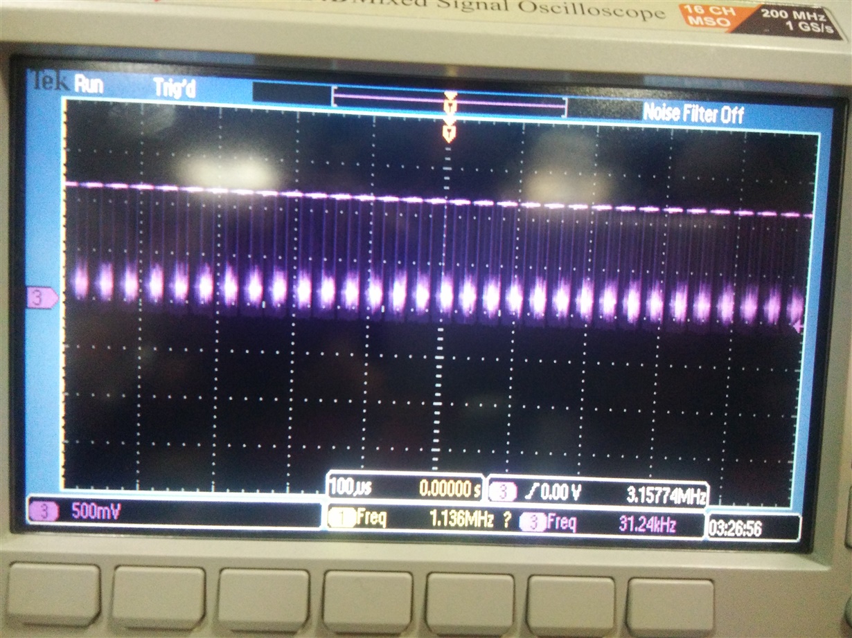
    We probed the data lanes of the working setup of AR0220 + SERDES on TDA2Px-EVM. Screenshot is attached. We probed on the single data lanes only as we do not have differential probes.

    We did not get similar waveforms on the data lanes on custom board. We observed that we are not getting driver callback in the CaptureISS example.

    Hi Mayank,

    We have already tried different combinations of CSI2 clock in "gSensorInterfaceInfo", but we are not getting any output.

    Regards,

    Abhay

  • If you are not getting the same waveform, it means that the sensor is not sending the data. In this case changing CSI2 settings will not help. Please check why the sensor is not sending the data. you may need to work with sensor vendor to get the right configuration for your custom board.
  • Hi Abhay,

    Are you able to capture / did you resolve sensor issue?

    Regards,
    Sujith
  • Hi Sujith,

    No we are still stuck with the sensor issue. We have verified the sensor register configurations with OnSemi as well. We are waiting for the SERDES board to be received from our client, which we will most probably get in the next week. We will test the sensor + SERDES on custom board and let you know the status.

    Regards,
    Abhay
  • Okay, could you please close this thread and start a new one if you have more issues?

    Regards,
    Sujith