This thread has been locked.

If you have a related question, please click the "Ask a related question" button in the top right corner. The newly created question will be automatically linked to this question.

TDA2P-ACD: Capture and Display 6 Sensors simultaneously (two CSI2 Ports)

Part Number: TDA2P-ACD

Hello Experts,

I found the following thread and was wondering if the functionality to run more than 4 sensors at the same time has been added to the PSDK since then.

e2e.ti.com/.../703535

Currently I try to run and display six sensors (IMX390) simultaneously on the TDA2Px + Fusion Board. Four sensors are connected to CSI2-PHY1 and two to CSI2-PHY2. Unfortunately the PSDK crashes when it reaches the function IssM2mIspLink_drvAllocFrames(). So I just want to make sure if it is possible at all to run these six sensors at the same time.

Regards,

Tobias

  • Hi Tobias,

    We dont have usecase demonstrating 6 channel capture.
    But we have added additional driver, which can help in processing more than 4 channels.
    We plan to add this feature in the upcoming release.

    Regards,
    Brijesh
  • Hi Brijesh,

    is it possible to get these drivers before the next release?

    And could please you tell me, what changes you had to make to get this working? I guess they were pretty complicated, right? I'm asking because I found some defines like ISSM2MISP_LINK_MAX_CH or ISS_SENSORS_MAX_CHANNEL and was wondering if those are related to those changes.

    Regards,
    Tobias
  • Hi Tobias,

    Drivers are already part of the 3.5 release. But there is no usecase demonstrating use of it.
    No it isn't just increasing the number of channels/handles. there are other changes required.

    Btw, why do you require more than 4 channels? What is the usecase? can you please provide some details?

    Rgds,
    Brijesh
  • Hi Brijesh,

    Oh, I see. I will take a look at the PSDK 3.5 then. Do the drivers handle this automatically or do I have to activate them somehow?

    A customer of ours wants a test system for sensors. Essentially they want to run as many of their selfmade sensors at the same time and check them under different environments (temperature, humidity etc.). We thought six sensors would be the optimal amount because of the six CSI2 data lanes we can use on PHY1 and PHY2.

    Regards,
    Tobias
  • Hi Tobias,

    Drivers does not handle it automatically, we need to pass additional channels (the ones which are more than 4) through one more memory to memory pass. 

    Rgds,

    Brijesh

  • Hey Brijesh,

    could you explain this a little more? Where do we have to set the channel passing? In ISP link init?
    Do we also have to adjust some defines (ISS_SENSORS_MAX_CHANNEL etc) then? Otherwise the PSDK would throw a assertion during sensor creation.

    Just to be clear: The last two channels are then processed by another device?
    Thanks for your help!

    Regards,
    Tobias

  • Hi Tobias,

    Not by another device, but by other module.
    Essentially, Capture can convert only 4 channels from MIPI format to Linear format, so for the rest 2 channels, we need to use another module to convert from MIPI format to linear format.

    Regards,
    Brijesh
  • Hi Brijesh,

    Ok, I understand that. But where exactly in the source code do we need to insert the changes to process the remaining two channels?
    You said, you iadjusted the driver for that, so the needed functions should be there already?

    Regards,
    Tobias
  • Hi Tobias,

    Driver is not adjusted, it is new driver that has been added. But still it is not supported in VSDK.

    Rgds,
    Brijesh
  • Hi Brijesh,

    thats unfortunate. Do you know where you have to enable/setup the new driver yet? Because earlier I managed to run a usecase where 2 sensors each ran on both PHYs. I was wondering if we could use that usecase and somehow expand it so that it uses the 6 sensors in total.

    Also do you plan to add a dedicated 4+CH usecase for the next PSDK release?

    Regards,
    Tobias
  • Hi Tobias,

    It is not problem in using 2 phys. But sure, you could start with this usecase.
    Capture module, CAL, has internal limitation. Because of which, we need to run addition channel through another driver.

    Rgds,
    Brijesh
  • Hey Brijesh,

    which module will then take part of the remaining channels?
    I also found the new define VPS_ISS_CALM2M_BUILD in the PSDK 3.5. Is that part of the new driver you wrote?

    Regards,
    Tobias
  • Hi Tobias,

    Yes, this is the new driver which will be used for the conversion.

    Rgds,

    Brijesh

  • Hey Brijesh,

    could you please tell me which module will process the remaining two channels then? Another CAL or do we use the same CAL and time-share it?
    I also noticed that capture CAL is named 'CAL_B', is there an 'CAL_A'?

    Also, could you give me a small guideline on how to use the new driver? The location where I have to add changes to the code, maybe?

    Thank you!

    Tobias

  • Hey Brijesh,

    I changed the driver create function in the ISP link to use VPS_M2M_ISS_INST_CAL_ISP to VPS_M2M_ISS_INST_CALM2M, so that ISP link uses the new drivers. Unfortunately I get an assertion while setting the pixel processing configs in CalSetPixProcCfg().

    (VPS_ISS_CAL_PIX_EXRCT_MIN != cfg->extract)

    Do I have to change some other parameters to make this work?

    Regards,
    Tobias
  • Hi Tobias,

    You need to set pixel extract config to 12bit mipi (VPS_ISS_CAL_PIX_EXRCT_B12_MIPI) format.

    Rgds,

    Brijesh

  • Hi Brijesh,

    it was already set to VPS_ISS_CAL_PIX_EXRCT_B12_MIPI in IssCaptureLink_drvSetDrvCfg. The first time CalSetPixProcCfg is called, the extract value is correct and I dont get the assertion.
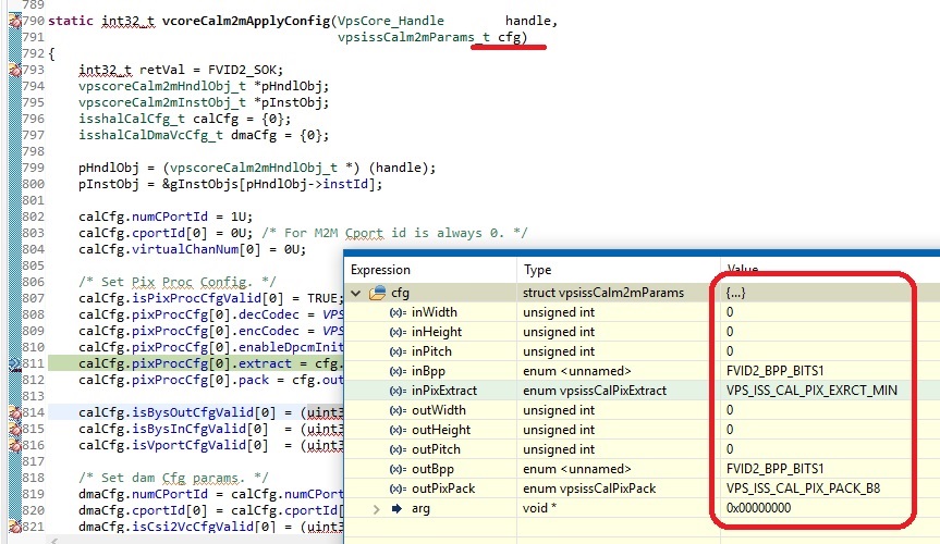
    But after the driver is created the problem is in vcoreCalm2mApplyConfig() in vpscore_calm2m.c. In the following line the pixel extract config is set to cfg.inPixExtract (also see attached image):

    calCfg.pixProcCfg[0].extract = cfg.inPixExtract;

    All other parameters from cfg are 0, so it seems this config isnt initialized. At least I couldn't find the init function. Do you know how to solve this?


    Thank you,
    Tobias

  • Hi Tobias,

    ok, so this is not in iss capture configrations. It seems you are trying to use new m2m path, which internally uses cal.

    we need to similarly configure cal even in m2m path. You could look into the example application in ti_components\drivers\pdk_01_10_01_06\packages\ti\drv\vps\examples\iss\m2mIssCal\src\ to understand how to configure it.  This example converts 12bit mipi to 12bit linear.

    Rgds,

    Brijesh  

  • Hi Brijesh,

    alright, I will take a look at the example.
    Just to be sure: this new m2m path makes it possible to use more than 4 sensors simultaneously?

    Regards,
    Tobias
  • Yes, it is in the way i explained earlier.
  • Hey Brijesh,

    I configured the CAL with IOCTL_VPS_ISS_CAL_M2M_SET_PARAMS and used the parameters from the example application. I only changed IN_WIDTH and IN_HEIGHT to 1920 and 1080.
    The usecase now runs without assertion, but the captured buffer is empty and the output frame is just green. The input frame into Capture Link from the sensor seems ok. and shows the correct image.

    1. Do you know why the output buffer is empty?
    2. Also, I replaced VPS_M2M_ISS_INST_CAL_ISP driver with VPS_M2M_ISS_INST_CALM2M. Is that correct or do I need to run both?

    Regards,
    Tobias


    My CAL settings:

    #define IN_WIDTH (1920U)
    #define IN_HEIGHT (1080U)
    #define IN_PITCH ((IN_WIDTH * 3) / 2)
    #define IN_FORMAT (FVID2_DF_BAYER_RAW)
    #define IN_BPP (FVID2_BPP_BITS12_PACKED_MIPI)
    #define IN_PIX_EXTRACT (VPS_ISS_CAL_PIX_EXRCT_B12_MIPI)
    #define OUT_WIDTH (IN_WIDTH)
    #define OUT_HEIGHT (IN_HEIGHT)
    #define OUT_PITCH (IN_WIDTH * 2)
    #define OUT_FORMAT (FVID2_DF_BAYER_RAW)
    #define OUT_BPP (FVID2_BPP_BITS16)
    #define OUT_PIX_PACK (VPS_ISS_CAL_PIX_PACK_B16)
  • I just saw in vcoreCalm2mPutFramesInternal() that calBuf.buffAddr[1], which is the CAL output buffer, is set to 0x00. There should be a valid buffer address in here, shouldnt it?

    Regards

  • Hi Tobias,

    Yes, output buffer address should not be 0, as i can corrupt the memory and does not output. 

    How are you using this new driver? have you integrated it in the VSDK?

    Please note that you need to allocate output buffer for this driver and pass it to the driver. 

    Regards,

    Brijesh

  • Hi Brijesh,

    yes, I integrated it into VSDK. I created the new driver instead of the old one in IssM2mIspLink_drvCreateDrv() and set the new CAL params in IssM2mIspLink_drvSetDrvParams().

    I think I'm missing the output buffer allocation then.
    Can you tell me where the allocation is usually executed (function/file in VSDK)?

    Regards,
    Tobias
  • Tobias,

    Each link allocates the output buffers, required for storing its output. I think it uses Utils_memAlloc API to allocate buffers from the shared meory, SR1. You could look into the iss capture link, alloc, API to get the idea about it.

    Rgds,
    Brijesh
  • Hi Brijesh,

    I found the function X_drvAllocFrames() in ISS Capture and ISP Link where the frames are allocated with Utils_memAlloc, as you said. Is this where I need to allocate the CAL output buffer, too?

    Does the CAL input buffer (calBuf.buffAddr[0]) also need to be allocated? I'm asking because it apparently contains correct buffer addresses. And I was searching for its allocation to find the right place to alloc the output frame, too.

    Regards
  • Hi Tobias,

    Yes, you could use this function to allocate the output buffers. The input buffer can come from the capture module, which overhear could be CAL, and then once the processing is finished, you could return capture buffer back to CAL module.

    This similar flow is used in all mem2mem operations.

    Rgds,
    Brijesh