This thread has been locked.

If you have a related question, please click the "Ask a related question" button in the top right corner. The newly created question will be automatically linked to this question.

AM5K2E04: Boot Up Duration from Reset to U-Boot

Part Number: AM5K2E04

Hello,


Analyzing the boot procedure of a TI AM5K2E04 we tumbled over an unexpectedly long period of time between the end of the reset sequence and the entrance of U-Boot.

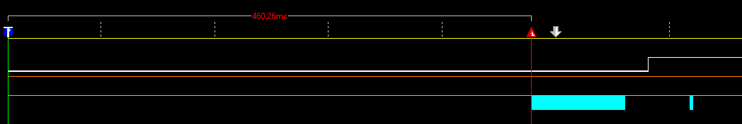
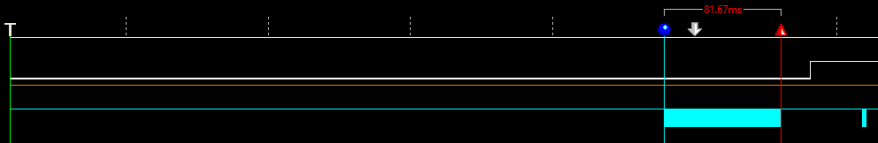
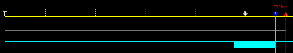
BOOTCOMPLETE pin is used to indicate the beginning of U-Boot function board_init_f(), where we set the BOOTCOMPLETE register at address 0x0262013C to 0xFFFFFFFF to generate a rising edge of BOOTCOMPLETE pin (pin AF31).

Between the end of the reset (rising edge of RESETSTAT#, pin AH29) and the entrance of board_init_f() a duration as long as 560 ms elapses (measured with oscilloscope). We can't explain this timespan to ourselves, as we for example expect a duration of about 60 ms to copy the U-Boot (about 150 kB in size); we are using EMIF Boot mode.

Is it plausible that almost 600 ms elapse from the end of reset to the entrance of board_init_f()? What’s going on during this time?


Thanks, best regards

Lennart

  • Hi,

    I have the same questions as the ones I asked on the other thread you've opened:

    Do you observe this on K2E EVM or a custom board? Which Processor SDK Linux version are you using?

    Do you see the same behavior when your board is connected to CCS via JTAG and board initialization is done by GEL files?

    Best Regards,
    Yordan
  • Dear Yordan,

    Gerald here; I'm a colleague of Lennart from our department which is in charge of the embedded software.
    To answer your question:

    1. We're using our own board
    2. We do not use the Processor SDK Linux

    We're analyzing the Keystone Reset procedure because boot performance is critical to our product.

    To provide some more details:
    Our Keystone2 is connected via EMIF16 to a NOR Flash and the boot process is controlled by an external logic (namely a CPLD which manages the boot sequence). The NOR Flash holds UBoot as a standard boot loader; we use UBoot 2016-05 as a base with slight modifications in the later boot stages. The effect described by Lennart is observed in the very early boot stages.

    The BOOTMODE[15:0] pins (DEVSTAT[16:1])are set to 00011-1000110011, which means:

    DEVSTAT[4:1] = 0011 ==> Use EMIF16 as boot device
    DEVSTAT[7:5] = 011 ==> Sys PLL for 100Mhz input clock
    DEVSTAT[8] = 0 ==> ARM Boot Master
    DEVSTAT[10:9] = 10 ==> Use EMIF16 ChipSelect4 (CE2)
    DEVSTAT[11] = -
    DEVSTAT[12] = 1 ==> Use 16-bit accesses on EMIf16
    DEVSTAT[13] = 1 ==> Extended Wait Enabled
    DEVSTAT[15:14] = 00 ==> Use 0x0 as base address
    DEVSTAT[16] = 0 ==> Use EMIF16 as boot device

    The boot sequence created by our CPLD looks like this:
    t_0 = 0 s: \POR pin is released (low -> high)
    t_1 = 100 µs: \RESETFULL pin is released (low -> high); Boot mode pins -> high Z
    t_2 = 200 µs: \RESET pin is released (low -> high)

    Using a scope, we measure the time from t_0 and the time when the DDR controller is reset by SW which is more or less immediately after board_init_f() is called in UBoot.

    Of course, the very first steps of UBoot take a few microseconds. And of course, the Keystone ROM bootloader needs some time to copy UBoot from EMIF16/Flash to internal SRAM. But 560ms is *way* above anything we'd expect. So we're wondering if this is some software effect inside the ROM bootloader or a possible HW effect which takes place even before the ROM bootloader starts.

    Cheers,
    Gerald
  • Hi, Gerald,

    I am not sure what would cause the long elapse time. Let me see what I get from our EVM.

    Rex
  • Hi, Gerald,

    I just disucssed this with our HW engineer. Could you measure the time to see how long it takes to read from EMIF NOR, from the first chip select to the last block read?

    After RESETSTAT# goes high, the EMIF PLL is configured to the default max values. We did a calculation based on K2E at 25MHz, The EMIF NOR read will take about 3.5us. For 158KB, it takes about 553 ms.

    If it is the case, you may want to load a very small ROM code to configure the NOR to higher speed than using the default values. Then, load the rest of the u-boot code which may improve the load time.

    Rex
  • Hi Rex,

    thanks for your answer.
    Our HW guys will measure the EMIF16 access time by monotoring the CS signal and we'll post the results as soon as they are available.

    HoweverI have my doubts that the EMIF16 transfer time is the reason here. Currently our UBoot is indeed around 160KB large and we see this delay of roughly 600ms. To check the influence of the UBoot size I've simply doubled it in size to ~320KB by adding some random data. When we use the double-size UBoot, the boot time increases from ~600ms to ~700ms (Lennart has the exact numbers).

    So according to this, the UBoot only accounts for about 100ms, leavin ~500ms a mystery :-D

    Anyway let's wait for the HW measurment results :-)

    Cheers,
    Gerald
  • Hi Rex,


    we did the measurement and found the following:

    yellow: RESET#

    orange: RESETSTAT#

    white: BOOTCOMPLETE, set in function board_init_f() as described above

    light blue: flash's ChipSelect# 

    The following three plots show the same boot sequence using a 152kB sized U-Boot (only the cursors differ). The plot starts with the rising edge of RESET#. We expect the blue block of the ChipSelect# signal occuring after about 460 ms and taking up about 81 ms to be the phase in which the U-Boot is copied. About 21 ms later board_init_f() is reached.


    With an enlarged U-Boot of about 218 kB this block takes up 117 ms as shown in the following plot:


    But the mysterious phase of 460 ms remains while copying the U-Boot does not seem to be the reason. Any ideas?


    Best regards,

    Lennart

  • Hi, Lennart,

    I am not seeing the plots. Could you try to insert them as attachments? The cut and paste won't work.

    Rex
  • Sorry, I updated my post
  • Hi Lennart,

    The current reset sequencing doesn't match the power up sequencing shown in the K2E data manual. The RESETz signal should be at a steady high state when PORz and RESETFULLz are released and should remain high until after the device has booted. I don't know if this is causing your long delays but it should be corrected before we attempt any further debug.

    Regards, Bill

  • Hi Bill,

    Thanks for your answer. We fixed our reset sequencing and also double checked the timings of the BOOTMODE pins, but the delay still remains.

    Our sequence now:

    t_0 = 0: RESET# low -> high

    t_1 = 100 µs: POR# low -> high

    t_2 = 200 µs: RESETFULL# low -> high

    BOOTMODE pins are held stable for another 400 ns after the rising edge of RESETFULL# (taken "12 transitions of the SYSCLK1 after the rising edge of RESETFULL#" and "maximum clock period is 33.33 nsec", although we expect SYSCLK1 to have a frequency of 1400 MHz).

    Best regards,

    Lennart

  • Hi Lennart,
    This is unusual behavior. We will try and get a board set up here to do some measurements and experimentation. Do you have the ability to select a different boot mode? I am curious to see if the delay is present with a different bootmode, preferably one that doesn't set up the PLL.
    Regards, Bill
  • Hi Bill,

    Thanks for your efforts, we're looking forward to the results of your investigations. Unfortunately we cannot switch to another boot mode without further ado.

    Best regards,

    Lennart

  • Hi, Lennart,

    Sorry for the slow response. Bill is out this week and we'll get on it as soon as he is back.

    Rex
  • Hi, Lennart,

    My apology for not being able to get on it yet. We'll try to work on it next week.

    Rex
  • Hi, Lennart,

    Just worked with Bill and trying to measure the signals. The EVM doesn't bring out some of the pins to measure, and we are not seeing BOOTCOMPLETE going high. We can't proceed further. The conclusion we have is that the SoC is running at lower speed hence takes longer time.

    Rex
  • Hi Rex,

    Thank you for your reply. Could you please provide some further information about the clock/speed we can expect during boot up and how to check it? As mentioned above we're actually expecting a frequency of 1400 MHz for SYSCLK1. If that is not the case, it may also affect other timings/settings.

    Best regards,

    Lennart

  • Hi Lennart,
    Based on your earlier posts you have a 100MHz clock and a 1400MHz part. Let's double check that the PLL is being configured correctly.  Do you have access to the SYSCLKOUT pin?  Can you measure the length of the control signals going to the flash memory used for boot? 
    Thanks, Bill

  • Hi Bill,

    Yes, our setup consists of a 100 MHz clock and a 1400 MHz part. The SYSCLKOUT pin is available for measurements. I'll provide results as soon as I can get my hands back on the board, presumably next week.

    To be sure: Does your question refer to the physical length of the signals' PCB tracks?

    Best regards,

    Lennart 

  • Hi Lennart,
    I'm sorry for the confusion. I was asking if you could measure the time pulses for CS and OE going to the FLASH. These should be in the default state during boot so it would help determine the frequency that the internal SYSCLK used by the EMIF interface.
    Regards, Bill
  • Hi Bill,

    Measuring the SYSCLKOUT Pin during the boot sequence we observe that the processor seems to run on only 100 MHz (SYSCLKOUT = 16.7 MHz = 100 MHz / 6) for a long period of time (approx. 450 ms):

    When the UBoot is copied, the frequency is ok (233 MHz = 1400 MHz / 6). As already mentioned in earlier posts the duration of this phase meets our expectations.

    Now we’re still unsure about the first period of time (marked "phase (1)" in the plot), as we expect the processor to run on the higher clock of 1400 MHz as configured with the bootmode pins.

    As a further explanation: the early accesses to the flash are not driven by the AM5K2, as also indicated by the EMIF_CE2# chip enable signal, which goes low (= active) when the UBoot is copied by the AM5K2.

    Can you provide any hints or explanations why the processor does not seem to configure the PLL right after reset to a frequency of 1400 MHz? The bootmode pins aren’t accessible for physical measurement but we already double-checked the belonging code of the CPLD which manages the pins.


    Best regards,

    Lennart

  • Hi, Lennart,

    We had internal discussions on this issue and found out a similar issue on a different device with another customer. If the NOR flash is connected to CE2 instead of CE0, the device will boot eventually after scanning through CE0 and CE1 address space and takes that long to reach the CE2 address range.

    That may explain the extra time.

    Rex
  • Hi, Lennart,

    I just had another discussion with TI ROM expert. The CE rollover issue was in early KS1 devices and may not apply to KS2 devices which had the option to select what CE to use. The ROM expert mentioned that there is a PLL issue (something called the band gap bug) which requires the ROM to do a full reset after coming up, wait a bit, and then reconfigure them. If you are using a secure device, the time is even longer. He didn't measure how long it took. His opinion is that the device may be stuck with the long boot up time, but you should get improvement by changing the reference clock to the supported max 212 MHz. Then, reconfigure the refclk back to 100MHz afterward.

    Hope this info is helpful.

    Rex
  • Hi Rex,

    thanks for your response and sorry for my late reply.
    To be sure to understand your suggestion right:
    1. Do you mean we should change our clock which is provided to the pins of the AM5K2 and which has a frequency of 100 MHz now to a higher value during the boot?
    Or do you refer to any settings “inside” the AM5K2, maybe the corresponding DEVSTAT/BOOTMODE bits as shown in Table 8-24 in SPRS864D?


    2. How is the max. value of 212 MHz derived?
    3. Is any more information about the mentioned “PLL issue” available?

    Thanks, best regards
    Lennart

  • Hi, Lennart,

    Sorry, it was a typo. The max frequency is 312 MHz, not 212MHz. When discussed with the ROM developer, he didn't realize that the time measurement you had. From the scope measurement, it won't make difference with higher frequency. We don't have the detail of the PLL issue. 

    Rex

  • Hi Rex,

    as we are still stuck with the problem I’d like to ask you for some more information:

    1.  Although you mentioned that not all pins are available for measurement on your evaluation board we think it should be possible to determine if you can reproduce the long delay.
    2. You mentioned that for „a secure device, the time is even longer“
      1. We are using an AM5K2E04XABD, X = Security Accelerator enabled / General Purpose device; do we have to expect the longer delay with this device, or does your statement only refer to devices labeled das „High Security device“?
      2. And if we are seeing the “longer delay”: what times can we expect using another device?

    Thanks, best regards
    Lennart


  • Dear Rex,

    we would really love to see this issue resolved; at least to the point where we have a decent explanation of this effect along with a statement whether this delay occurs in all variants of the K2 device or not.

    To give you some background:

    Our Keystone2-based product is used in the field of high-performance automotive controllers. Our customers are basically all major automotive OEMs and for them, boot performance of a the device is pretty important. We've invested quite some effort to push the boot time of our device way below 2000ms. Therefore, a(seemingly) unneccessary additional boot delay of >500ms *is* significant for us. If that problem cannot be solved we'd like to have at least a plausible explanation.

    Cheers,

    Gerald

  • Lennart Siekmann said:
     Although you mentioned that not all pins are available for measurement on your evaluation board we think it should be possible to determine if you can reproduce the long delay.

    The evaluation platform that we have for this device only has EMIF16 NAND boot connected. While we can put the device in EMIF16 XIP boot mode there is no parallel NOR flash interface connected so the option to test delay from first instruction in ROM to first instruction in uboot can`t be measured as in case of your board  

    Lennart Siekmann said:
    You mentioned that for „a secure device, the time is even longer“
    1. We are using an AM5K2E04XABD, X = Security Accelerator enabled / General Purpose device; do we have to expect the longer delay with this device, or does your statement only refer to devices labeled das „High Security device“?
    2. And if we are seeing the “longer delay”: what times can we expect using another device?

    You are using a general Purpose device with security accelerator enabled which is different from a High secure device on which the JTAGs are locked at reset and the boot ROM enforces authentication of digital signature along with loading for the image to the device. this is not the root cause of the boot delay that you are reporting.

    We are currently exploring the possibility of setting up the device in EMIF16 boot mode and measuring the time from first instruction in ROM to the first access to EMIF16 in CCS to see if this reveals additional information. Can you indicate how you are measuring the time from POR to first instruction in uboot. Can you indicate if you are using a SPL image with uboot that reconfigures the PLL before loading uboot ? what kind of parallel NOR flash are you using 8 bit or 16 bit ? Is their a Wait enable pin ? Please also share the full DEVSTAT settings that you are using.

    As you may know, in parallel NOR/ EMIF16 XIP boot the ROM on A15 only sets up PLL and EMIF IP and jumps to the base memory location of EMIF16 address space so the delay seems quite larger. 

    Regards,

    Rahul

  • Gerald, Lennart,

    We just setup the bootROM on the K2E EVM with EMIF NAND boot to load uboot to measure the boot time using CCS. We interrupted the normal boot process and connected to A15 using emulator and CCS and loaded the ROM symbols. We then reset the A15 core0 to reset the Program counter to jump back to first instruction in ROM and measured the time taken from the A15 to setup EMIF NAND and load uboot by setting a break point at bootExit..  

    This time was measured to be 62,375,077 cycles. Assuming ARM runs at 1 GHz for approximation, this translates to 62.375 milliseconds. However since the SOC initially boots in PLL bypass state. I measured the time until the PLL is configured is about 42 million clock cycles. So with OSCIN of 312.5MHz..

    Actual boot time = (42000000/312.5) + (23000000/1250)   = 152.8 ms 

    Can you repeat this experiment with EMIF16 NOR boot and let us know. Here are the ROM symbol locations where you can set HW break points.

    1. A15 ROM base address boot.s: 0x00000000

    2. chipConfigPLL : 0x1434

    3 BootExit: 0x0000bc0b  

    Screenshot: 

    Let me know if you have any questions with regards to this setup.

    Regards,

    Rahul

    PS: We don`t share the full ROM symbol table and source so you will need to locate the address in the disassembly view in CCS and set the HW break points.  Clock in CCS is located under Run Menu.

  • Given the above findings, I have additional follow up questions to understand the larger than expected boot delay with your setup.

    1. Have you confirmed to check NOR flash gets powered up before the SOC tries to access the flash? 

    2. Is the oscilloscope measurement from when you apply power to board or when the POR is asserted. 

    3. Can you confirm that board_init function is in first stage uboot/SPL code. We are assuming this is the first function that will execute after bootROM exits. Is that true? Are you adding a GPIO toggle in that function to measure the timing on the scope?

  • Hi Gerald, Lennart

    Do you have any updates on the questions posted by Rahul - we are hoping that we are able to help you sort this with some joint debug given we really do not have a way to replicate this on our EVM. 

    I will mark this post closed (resolved) for now since we have not heard from you for last 5 days - but it will automatically reopen when you post a follow up. 

    Please keep us posted.

    Regards

    Mukul 

  • Gerald, Lennart,

    Additional update on this issue. We had a internal discussion on this topic where we reviewed the information obtained from you. It appears that in one of the E2E threads where you have shared the scope shots, you are reading the SYSCLK/6 to be 16.67 MHz initially when the PLL is in bypass state . Our understanding earlier was that the SYSCLK on your custom board is 312.5 MHz can you indicate why the scope seems to suggest that the clock is 100 MHz.

    If the SYSCLK is indeed 100 Mhz then your observation seems to be consistent with our benchmark of 42 million cycles in ROM before PLL is configured for EMIF NAND boot. This will result in a delay of about ~420 ms  (measured is ~450 ms in your scope shot). Please clarify if the clock on your custom board is 100 Mhz or 312.5 Mhz.

    Regards,

    Rahul

  • Hello Rahul,

    yes, as we wrote our external clock runs with a frequency of 100 MHz. For testing purposes we switched to 312.5 MHz and could observe that the delay shrunk from 460 ms to 147 ms (which is exactly 460 ms * 100 MHz / 312,5 MHz) and matches your findings that the PLL needs about 42E6 cycles to come up.

    Now that this "mysterious phase" seems to be identified as the initialization of the PLL, a major question still persists:

    Is there any chance to speed this up (apart from the higher clock)? Maybe by using another device type?

    And could you please provide information about the correlation of the reset signals (RESET#, POR#, RESETFULL#) and the behavior of the PLL? In other words: if we do not release all three resets more or less at the same time (delayed by 100 µs) as we do currently, is there any possibility to start the PLL configuration at an earlier point in time and trigger the actual boot procedure separately?

    Best regards

    Lennart

  • Lennart,

    Thanks for confirming my observations from the EVM with your setup so it does appear that the time taken until ROM configures the PLL is the root cause for the failure. As far as ROM code is concerned, we can`t modify this chip behavior.

    I will let our hardware experts provide their inputs on the power sequencing question as this is not my area of expertise.

    Regards,

    Rahul

  • Hi Rahul,

    are there any news concerning the reset sequence?

    Best regards

    Lennart

  • Lennart,

    There appears to be some misunderstanding.  The delay of 42e6 cycles that you and Rahul have both measured is the delay from start of BOOTROM execution to the point where the PLL has been reconfigured.  This is not a reset hardware logic delay or a PLL reconfiguration and lock delay.  These hardware delays are very short (<1ms).  The delay of 42e6 cycles is a BOOTROM execution delay that cannot be shortened.  However, as you have validated, this fixed cycle delay can be minimized by increasing the BYPASS clock rate to the maximum allowed rate of 312.5MHz.  This cycle delay is same for all K2E devices.

    Tom