This thread has been locked.

If you have a related question, please click the "Ask a related question" button in the top right corner. The newly created question will be automatically linked to this question.

RTOS/AM3359: Problem using UART4 on ICEV2 with PRU-ICSS pinmux

Part Number: AM3359
Other Parts Discussed in Thread: TMDSICE3359

Tool/software: TI-RTOS

I have a project that is built off of the NIMU_ICSS Example Project using the PRU as a dual MAC. The PRU functionality works well and is using UART3 for debug terminal. 

I am attempting to simply enable UART4 which is pinned out to header J3 on the development board. If I call the initialization code below I do not see any output on the UART Tx line. 

UART_Handle handle;
UART_Params params;

UART_Params_init(&params);
params.baudRate = 115200;
params.writeDataMode = UART_DATA_BINARY;
params.readDataMode = UART_DATA_BINARY;
params.readReturnMode = UART_RETURN_FULL;
params.readEcho = UART_ECHO_ON;
handle = UART_open(4, &params);
if (!handle) {
System_printf("UART did not open");
}

// new UART should be open, so lets send some data to it
const unsigned char testStr[] = "Test: Hello World!\n";

int32_t retVal = UART_write(handle, testStr, sizeof(testStr));
UART_printf("new UART printed %d characters\n", retVal);

In main I am calling the following Board_init cfg:


Board_initCfg cfg = BOARD_INIT_PLL| BOARD_INIT_MODULE_CLOCK | BOARD_INIT_DDR | BOARD_INIT_ICSS_PINMUX | BOARD_INIT_UART_STDIO | BOARD_INIT_ICSS_ETH_PHY;
ret = Board_init(cfg);
if (ret != BOARD_SOK)
{
UART_printf("main: Board_init returned error code: %d\n", ret);
return -2;
}

If I examine the pinmux file, iceV2AM335x_pinmux.c, I see that UART4 should be being configured:

/* UART */
status = PINMUXModuleConfig(CHIPDB_MOD_ID_UART, 1U, NULL);
if(S_PASS == status)
{
status = PINMUXModuleConfig(CHIPDB_MOD_ID_UART, 3U, NULL);
}
if(S_PASS == status)
{
status = PINMUXModuleConfig(CHIPDB_MOD_ID_UART, 4U, NULL);
}

So... what is the obvious thing I am missing? 

  • Hello,
    did you use the function "PRCMModuleEnable()" in some other part of your code?
    It should be called in order to enable the UART instance.
    BR
    Michail

  • Michail,

    Thanks for the reply. In main I am calling:

    Board_initCfg cfg = BOARD_INIT_PLL| BOARD_INIT_MODULE_CLOCK | BOARD_INIT_DDR | BOARD_INIT_ICSS_PINMUX | BOARD_INIT_UART_STDIO | BOARD_INIT_ICSS_ETH_PHY;
    ret = Board_init(cfg);

    Would this not call Board_moduleClockInit() as configured in the icev2AM335x.c file? This file includes the following line:

    status = PRCMModuleEnable(CHIPDB_MOD_ID_UART, 4U, 0U);

    So, I believe the clock for the module is being configured.

    Let me know if you have a suggestion on how to confirm this, or further suggestions.

    Thank you!
  • Nicholas,

    Couple of minor sanity checks:
    1. To confirm the pinmux setup, have you read back the Mux mode to confirm Have you imported the pinmux project and checked the pin setup has both enabled.
    2. Does the UART work with PRU ICSS related pinmux taken out . If that is the case there is some conflict.
    3. Software numbers UART instance from 0, N-1 so make sure that you are using the correct instance.
    4. How are you testing the UART functionality. there is only one debug UART so have you hooked up a scope to TX and RX.

    Please refer to this document that walks user though all steps to enable use of custom UART instance to see if you missed any step:
    www.ti.com/.../sprac32a.pdf

    Hope this helps.

    Regards,
    Rahul
  • You say:

    1. To confirm the pinmux setup, have you read back the Mux mode to confirm Have you imported the pinmux project and checked the pin setup has both enabled.

    If you are referring to the PinMux utility, yes I have imported the icev2_config.pinmux file and regenerated the pinmux files (attached) according to the instructions in the pdf (obviously changining from Beaglebone to am335x_icev2). And how do I read back the pinmux mode? That would be very helpful.

    2. Does the UART work with PRU ICSS related pinmux taken out . If that is the case there is some conflict.

    I have now switched over to using the UART example project. The UART3 works correctly, through the USB -serial interface, as my debug output. So my boardCfg now looks like:

       boardCfg = BOARD_INIT_PINMUX_CONFIG |

                  BOARD_INIT_MODULE_CLOCK  |

                  BOARD_INIT_UART_STDIO;

    And I am still not able to initialize UART4.

    3. Software numbers UART instance from 0, N-1 so make sure that you are using the correct instance.

    Yes, I am trying to initialize instance 4 which comes out to header J3 pin 7 and pin 8 on the ICEV2 board. So I am calling

    handle = UART_open(4, &params);

    Is this the correct instance index? This seems correct to me.

    4. How are you testing the UART functionality. there is only one debug UART so have you hooked up a scope to TX and RX.

    I have a scope on both TX and RX. I see no wiggle...

    8561.am335x_icev2_pinmux_data.c
    /**
     * Note: This file was auto-generated by TI PinMux on 4/24/2019 at 6:04:48 AM.
     *
     * \file  am335x_pinmux_data.c
     *
     * \brief  This file contains the pin mux configurations for the boards.
     *         These are prepared based on how the peripherals are extended on
     *         the boards.
     *
     * \copyright Copyright (CU) 2019 Texas Instruments Incorporated -
     *             http://www.ti.com/
     */
    
    /* ========================================================================== */
    /*                             Include Files                                  */
    /* ========================================================================== */
    #include "types.h"
    #include "pinmux.h"
    #include "am335x_pinmux.h"
    
    /** Peripheral Pin Configurations */
    
    #ifndef BUILDCFG_MOD_UART
    #define BUILDCFG_MOD_UART
    #endif /* BUILDCFG_MOD_UART */
    
    #ifndef BUILDCFG_MOD_CPSW
    #define BUILDCFG_MOD_CPSW
    #endif /* BUILDCFG_MOD_CPSW */
    
    #ifndef BUILDCFG_MOD_GPIO
    #define BUILDCFG_MOD_GPIO
    #endif /* BUILDCFG_MOD_GPIO */
    
    #ifndef BUILDCFG_MOD_I2C
    #define BUILDCFG_MOD_I2C
    #endif /* BUILDCFG_MOD_I2C */
    
    #ifndef BUILDCFG_MOD_MCSPI
    #define BUILDCFG_MOD_MCSPI
    #endif /* BUILDCFG_MOD_MCSPI */
    
    #ifndef BUILDCFG_MOD_MMCSD
    #define BUILDCFG_MOD_MMCSD
    #endif /* BUILDCFG_MOD_MMCSD */
    
    
    #if defined(BUILDCFG_MOD_UART)
    
    static pinmuxPerCfg_t gUart0PinCfg[] =
    {
        {
           /* UART 0 -> uart0_rxd -> E15 */
           PIN_UART0_RXD, 0, \
           ( \
               PIN_MODE(0) | \
               ((PIN_PULL_UD_EN | PIN_RX_ACTIVE) & (~PIN_PULL_TYPE_SEL)) \
           ) \
        },
        {
           /* UART 0 -> uart0_txd -> E16 */
           PIN_UART0_TXD, 0, \
           ( \
               PIN_MODE(0) | \
               ((PIN_PULL_UD_EN) & (~PIN_PULL_TYPE_SEL & ~PIN_RX_ACTIVE)) \
           ) \
        },
        {PINMUX_INVALID_PIN}
    };
    
    static pinmuxPerCfg_t gUart1PinCfg[] =
    {
        {
           /* UART1 -> uart1_rxd -> D16 */
           PIN_UART1_RXD, 0, \
           ( \
               PIN_MODE(0) | \
               ((PIN_PULL_UD_EN | PIN_RX_ACTIVE) & (~PIN_PULL_TYPE_SEL)) \
           ) \
        },
        {
           /* UART1 -> uart1_txd -> D15 */
           PIN_UART1_TXD, 0, \
           ( \
               PIN_MODE(0) | \
               ((PIN_PULL_UD_EN) & (~PIN_PULL_TYPE_SEL & ~PIN_RX_ACTIVE)) \
           ) \
        },
        {PINMUX_INVALID_PIN}
    };
    
    static pinmuxPerCfg_t gUart3PinCfg[] =
    {
        {
           /* UART3 -> uart3_rxd -> L17 */
           PIN_GMII1_RXD3, 0, \
           ( \
               PIN_MODE(1) | \
               ((PIN_PULL_UD_EN | PIN_RX_ACTIVE) & (~PIN_PULL_TYPE_SEL)) \
           ) \
        },
        {
           /* UART3 -> uart3_txd -> L16 */
           PIN_GMII1_RXD2, 0, \
           ( \
               PIN_MODE(1) | \
               ((PIN_PULL_UD_EN) & (~PIN_PULL_TYPE_SEL & ~PIN_RX_ACTIVE)) \
           ) \
        },
        {PINMUX_INVALID_PIN}
    };
    
    static pinmuxPerCfg_t gUart4PinCfg[] =
    {
        {
           /* UART 4 -> uart4_rxd -> J18 */
           PIN_GMII1_TXD3, 0, \
           ( \
               PIN_MODE(3) | \
               ((PIN_PULL_UD_EN | PIN_RX_ACTIVE) & (~PIN_PULL_TYPE_SEL)) \
           ) \
        },
        {
           /* UART 4 -> uart4_txd -> K15 */
           PIN_GMII1_TXD2, 0, \
           ( \
               PIN_MODE(3) | \
               ((PIN_PULL_UD_EN) & (~PIN_PULL_TYPE_SEL & ~PIN_RX_ACTIVE)) \
           ) \
        },
        {PINMUX_INVALID_PIN}
    };
    
    static pinmuxModuleCfg_t gUartPinCfg[] =
    {
        {0, TRUE, gUart0PinCfg},
        {1, TRUE, gUart1PinCfg},
        {3, TRUE, gUart3PinCfg},
        {4, TRUE, gUart4PinCfg},
        {CHIPDB_INVALID_INSTANCE_NUM}
    };
    
    #endif /* if defined(BUILDCFG_MOD_UART) */
    
    #if defined(BUILDCFG_MOD_CPSW)
    
    static pinmuxPerCfg_t gCpsw0PinCfg[] =
    {
        {
           /* MDIO -> mdio_clk -> M18 */
           PIN_MDIO_CLK, 0, \
           ( \
               PIN_MODE(0) | \
               ((PIN_PULL_UD_EN) & (~PIN_PULL_TYPE_SEL & ~PIN_RX_ACTIVE)) \
           ) \
        },
        {
           /* MDIO -> mdio_data -> M17 */
           PIN_MDIO_DATA, 0, \
           ( \
               PIN_MODE(0) | \
               ((PIN_PULL_UD_EN | PIN_RX_ACTIVE) & (~PIN_PULL_TYPE_SEL)) \
           ) \
        },
        {
           /* RMII1 -> rmii1_crs_dv -> H17 */
           PIN_GMII1_CRS, 0, \
           ( \
               PIN_MODE(1) | \
               ((PIN_PULL_UD_EN | PIN_RX_ACTIVE) & (~PIN_PULL_TYPE_SEL)) \
           ) \
        },
        {
           /* RMII1 -> rmii1_rxer -> J15 */
           PIN_GMII1_RXER, 0, \
           ( \
               PIN_MODE(1) | \
               ((PIN_PULL_UD_EN | PIN_RX_ACTIVE) & (~PIN_PULL_TYPE_SEL)) \
           ) \
        },
        {
           /* RMII1 -> rmii1_txen -> J16 */
           PIN_GMII1_TXEN, 0, \
           ( \
               PIN_MODE(1) | \
               ((PIN_PULL_UD_EN) & (~PIN_PULL_TYPE_SEL & ~PIN_RX_ACTIVE)) \
           ) \
        },
        {
           /* RMII1 -> rmii1_txd0 -> K17 */
           PIN_GMII1_TXD0, 0, \
           ( \
               PIN_MODE(1) | \
               ((PIN_PULL_UD_EN) & (~PIN_PULL_TYPE_SEL & ~PIN_RX_ACTIVE)) \
           ) \
        },
        {
           /* RMII1 -> rmii1_txd1 -> K16 */
           PIN_GMII1_TXD1, 0, \
           ( \
               PIN_MODE(1) | \
               ((PIN_PULL_UD_EN) & (~PIN_PULL_TYPE_SEL & ~PIN_RX_ACTIVE)) \
           ) \
        },
        {
           /* RMII1 -> rmii1_rxd0 -> M16 */
           PIN_GMII1_RXD0, 0, \
           ( \
               PIN_MODE(1) | \
               ((PIN_PULL_UD_EN | PIN_RX_ACTIVE) & (~PIN_PULL_TYPE_SEL)) \
           ) \
        },
        {
           /* RMII1 -> rmii1_rxd1 -> L15 */
           PIN_GMII1_RXD1, 0, \
           ( \
               PIN_MODE(1) | \
               ((PIN_PULL_UD_EN | PIN_RX_ACTIVE) & (~PIN_PULL_TYPE_SEL)) \
           ) \
        },
        {
           /* RMII1 -> rmii1_refclk -> H18 */
           PIN_RMII1_REFCLK, 0, \
           ( \
               PIN_MODE(0) | \
               ((PIN_PULL_UD_EN | PIN_RX_ACTIVE) & (~PIN_PULL_TYPE_SEL)) \
           ) \
        },
        {
           /* RMII2 -> rmii2_crs_dv -> T17 */
           PIN_GPMC_WAIT0, 0, \
           ( \
               PIN_MODE(3) | \
               ((PIN_PULL_UD_EN | PIN_RX_ACTIVE) & (~PIN_PULL_TYPE_SEL)) \
           ) \
        },
        {
           /* RMII2 -> rmii2_rxer -> U17 */
           PIN_GPMC_WPN, 0, \
           ( \
               PIN_MODE(3) | \
               ((PIN_PULL_UD_EN | PIN_RX_ACTIVE) & (~PIN_PULL_TYPE_SEL)) \
           ) \
        },
        {
           /* RMII2 -> rmii2_txen -> R13 */
           PIN_GPMC_A0, 0, \
           ( \
               PIN_MODE(3) | \
               ((PIN_PULL_UD_EN) & (~PIN_PULL_TYPE_SEL & ~PIN_RX_ACTIVE)) \
           ) \
        },
        {
           /* RMII2 -> rmii2_txd0 -> V15 */
           PIN_GPMC_A5, 0, \
           ( \
               PIN_MODE(3) | \
               ((PIN_PULL_UD_EN) & (~PIN_PULL_TYPE_SEL & ~PIN_RX_ACTIVE)) \
           ) \
        },
        {
           /* RMII2 -> rmii2_txd1 -> R14 */
           PIN_GPMC_A4, 0, \
           ( \
               PIN_MODE(3) | \
               ((PIN_PULL_UD_EN) & (~PIN_PULL_TYPE_SEL & ~PIN_RX_ACTIVE)) \
           ) \
        },
        {
           /* RMII2 -> rmii2_rxd0 -> V17 */
           PIN_GPMC_A11, 0, \
           ( \
               PIN_MODE(3) | \
               ((PIN_PULL_UD_EN | PIN_RX_ACTIVE) & (~PIN_PULL_TYPE_SEL)) \
           ) \
        },
        {
           /* RMII2 -> rmii2_rxd1 -> T16 */
           PIN_GPMC_A10, 0, \
           ( \
               PIN_MODE(3) | \
               ((PIN_PULL_UD_EN | PIN_RX_ACTIVE) & (~PIN_PULL_TYPE_SEL)) \
           ) \
        },
        {
           /* RMII2 -> rmii2_refclk -> H16 */
           PIN_GMII1_COL, 0, \
           ( \
               PIN_MODE(1) | \
               ((PIN_PULL_UD_EN | PIN_RX_ACTIVE) & (~PIN_PULL_TYPE_SEL)) \
           ) \
        },
        {PINMUX_INVALID_PIN}
    };
    
    static pinmuxModuleCfg_t gCpswPinCfg[] =
    {
        {0, TRUE, gCpsw0PinCfg},
        {CHIPDB_INVALID_INSTANCE_NUM}
    };
    
    #endif /* if defined(BUILDCFG_MOD_CPSW) */
    
    #if defined(BUILDCFG_MOD_GPIO)
    
    static pinmuxPerCfg_t gGpio0PinCfg[] =
    {
        {
           /* GPIO0 -> gpio0[7] -> C18 */
           PIN_ECAP0_IN_PWM0_OUT, 7, \
           ( \
               PIN_MODE(7) | \
               ((PIN_PULL_UD_EN | PIN_RX_ACTIVE) & (~PIN_PULL_TYPE_SEL)) \
           ) \
        },
        {
           /* GPIO0 -> gpio0[18] -> F16 */
           PIN_USB0_DRVVBUS, 18, \
           ( \
               PIN_MODE(7) | \
               ((PIN_PULL_UD_EN | PIN_RX_ACTIVE) & (~PIN_PULL_TYPE_SEL)) \
           ) \
        },
        {PINMUX_INVALID_PIN}
    };
    
    static pinmuxPerCfg_t gGpio1PinCfg[] =
    {
        {
           /* GPIO1 -> gpio1[9] -> E17 */
           PIN_UART0_RTSN, 9, \
           ( \
               PIN_MODE(7) | \
               ((PIN_PULL_UD_EN | PIN_RX_ACTIVE) & (~PIN_PULL_TYPE_SEL)) \
           ) \
        },
        {
           /* GPIO1 -> gpio1[30] -> U9 */
           PIN_GPMC_CSN1, 30, \
           ( \
               PIN_MODE(7) | \
               ((PIN_PULL_UD_EN | PIN_RX_ACTIVE) & (~PIN_PULL_TYPE_SEL)) \
           ) \
        },
        {PINMUX_INVALID_PIN}
    };
    
    static pinmuxPerCfg_t gGpio3PinCfg[] =
    {
        {
           /* GPIO3 -> gpio3[9] -> K18 */
           PIN_GMII1_TXCLK, 9, \
           ( \
               PIN_MODE(7) | \
               ((PIN_PULL_UD_EN | PIN_RX_ACTIVE) & (~PIN_PULL_TYPE_SEL)) \
           ) \
        },
        {
           /* GPIO3 -> gpio3[10] -> L18 */
           PIN_GMII1_RXCLK, 10, \
           ( \
               PIN_MODE(7) | \
               ((PIN_PULL_UD_EN | PIN_RX_ACTIVE) & (~PIN_PULL_TYPE_SEL)) \
           ) \
        },
        {
           /* GPIO3 -> gpio3[21] -> A14 */
           PIN_MCASP0_AHCLKX, 21, \
           ( \
               PIN_MODE(7) | \
               ((PIN_PULL_UD_EN | PIN_RX_ACTIVE) & (~PIN_PULL_TYPE_SEL)) \
           ) \
        },
        {PINMUX_INVALID_PIN}
    };
    
    static pinmuxModuleCfg_t gGpioPinCfg[] =
    {
        {0, TRUE, gGpio0PinCfg},
        {1, TRUE, gGpio1PinCfg},
        {3, TRUE, gGpio3PinCfg},
        {CHIPDB_INVALID_INSTANCE_NUM}
    };
    
    #endif /* if defined(BUILDCFG_MOD_GPIO) */
    
    #if defined(BUILDCFG_MOD_I2C)
    
    static pinmuxPerCfg_t gI2c0PinCfg[] =
    {
        {
           /* I2C 0 -> I2C0_SCL -> C16 */
           PIN_I2C0_SCL, 0, \
           ( \
               PIN_MODE(0) | \
               ((PIN_PULL_UD_EN | PIN_RX_ACTIVE) & (~PIN_PULL_TYPE_SEL)) \
           ) \
        },
        {
           /* I2C 0 -> I2C0_SDA -> C17 */
           PIN_I2C0_SDA, 0, \
           ( \
               PIN_MODE(0) | \
               ((PIN_PULL_UD_EN | PIN_RX_ACTIVE) & (~PIN_PULL_TYPE_SEL)) \
           ) \
        },
        {PINMUX_INVALID_PIN}
    };
    
    static pinmuxModuleCfg_t gI2cPinCfg[] =
    {
        {0, TRUE, gI2c0PinCfg},
        {CHIPDB_INVALID_INSTANCE_NUM}
    };
    
    #endif /* if defined(BUILDCFG_MOD_I2C) */
    
    #if defined(BUILDCFG_MOD_MCSPI)
    
    static pinmuxPerCfg_t gMcspi0PinCfg[] =
    {
        {
           /* SPI0 -> spi0_sclk -> A17 */
           PIN_SPI0_SCLK, 0, \
           ( \
               PIN_MODE(0) | \
               ((PIN_PULL_UD_EN | PIN_RX_ACTIVE) & (~PIN_PULL_TYPE_SEL)) \
           ) \
        },
        {
           /* SPI0 -> spi0_d0 -> B17 */
           PIN_SPI0_D0, 0, \
           ( \
               PIN_MODE(0) | \
               ((PIN_PULL_UD_EN | PIN_RX_ACTIVE) & (~PIN_PULL_TYPE_SEL)) \
           ) \
        },
        {
           /* SPI0 -> spi0_d1 -> B16 */
           PIN_SPI0_D1, 0, \
           ( \
               PIN_MODE(0) | \
               ((PIN_PULL_UD_EN | PIN_RX_ACTIVE) & (~PIN_PULL_TYPE_SEL)) \
           ) \
        },
        {
           /* SPI0 -> spi0_cs0 -> A16 */
           PIN_SPI0_CS0, 0, \
           ( \
               PIN_MODE(0) | \
               ((PIN_PULL_UD_EN | PIN_RX_ACTIVE) & (~PIN_PULL_TYPE_SEL)) \
           ) \
        },
        {PINMUX_INVALID_PIN}
    };
    
    static pinmuxModuleCfg_t gMcspiPinCfg[] =
    {
        {0, TRUE, gMcspi0PinCfg},
        {CHIPDB_INVALID_INSTANCE_NUM}
    };
    
    #endif /* if defined(BUILDCFG_MOD_MCSPI) */
    
    #if defined(BUILDCFG_MOD_MMCSD)
    
    static pinmuxPerCfg_t gMmcsd0PinCfg[] =
    {
        {
           /* MMC 0 -> mmc0_clk -> G17 */
           PIN_MMC0_CLK, 0, \
           ( \
               PIN_MODE(0) | \
               ((PIN_PULL_UD_EN | PIN_RX_ACTIVE) & (~PIN_PULL_TYPE_SEL)) \
           ) \
        },
        {
           /* MMC 0 -> mmc0_cmd -> G18 */
           PIN_MMC0_CMD, 0, \
           ( \
               PIN_MODE(0) | \
               ((PIN_PULL_UD_EN | PIN_RX_ACTIVE) & (~PIN_PULL_TYPE_SEL)) \
           ) \
        },
        {
           /* MMC 0 -> mmc0_dat0 -> G16 */
           PIN_MMC0_DAT0, 0, \
           ( \
               PIN_MODE(0) | \
               ((PIN_PULL_UD_EN | PIN_RX_ACTIVE) & (~PIN_PULL_TYPE_SEL)) \
           ) \
        },
        {
           /* MMC 0 -> mmc0_dat1 -> G15 */
           PIN_MMC0_DAT1, 0, \
           ( \
               PIN_MODE(0) | \
               ((PIN_PULL_UD_EN | PIN_RX_ACTIVE) & (~PIN_PULL_TYPE_SEL)) \
           ) \
        },
        {
           /* MMC 0 -> mmc0_dat2 -> F18 */
           PIN_MMC0_DAT2, 0, \
           ( \
               PIN_MODE(0) | \
               ((PIN_PULL_UD_EN | PIN_RX_ACTIVE) & (~PIN_PULL_TYPE_SEL)) \
           ) \
        },
        {
           /* MMC 0 -> mmc0_dat3 -> F17 */
           PIN_MMC0_DAT3, 0, \
           ( \
               PIN_MODE(0) | \
               ((PIN_PULL_UD_EN | PIN_RX_ACTIVE) & (~PIN_PULL_TYPE_SEL)) \
           ) \
        },
        {
           /* MMC 0 -> mmc0_sdcd -> C15 */
           PIN_SPI0_CS1, 0, \
           ( \
               PIN_MODE(5) | \
               ((PIN_PULL_UD_EN | PIN_RX_ACTIVE) & (~PIN_PULL_TYPE_SEL)) \
           ) \
        },
        {PINMUX_INVALID_PIN}
    };
    
    static pinmuxModuleCfg_t gMmcsdPinCfg[] =
    {
        {0, TRUE, gMmcsd0PinCfg},
        {CHIPDB_INVALID_INSTANCE_NUM}
    };
    
    #endif /* if defined(BUILDCFG_MOD_MMCSD) */
    
    
    pinmuxBoardCfg_t gIceV2PinmuxData[] =
    {
    #if defined(BUILDCFG_MOD_UART)
        {CHIPDB_MOD_ID_UART, gUartPinCfg},
    #endif /* if defined(BUILDCFG_MOD_UART) */
    #if defined(BUILDCFG_MOD_CPSW)
        {CHIPDB_MOD_ID_CPSW, gCpswPinCfg},
    #endif /* if defined(BUILDCFG_MOD_CPSW) */
    #if defined(BUILDCFG_MOD_GPIO)
        {CHIPDB_MOD_ID_GPIO, gGpioPinCfg},
    #endif /* if defined(BUILDCFG_MOD_GPIO) */
    #if defined(BUILDCFG_MOD_I2C)
        {CHIPDB_MOD_ID_I2C, gI2cPinCfg},
    #endif /* if defined(BUILDCFG_MOD_I2C) */
    #if defined(BUILDCFG_MOD_MCSPI)
        {CHIPDB_MOD_ID_MCSPI, gMcspiPinCfg},
    #endif /* if defined(BUILDCFG_MOD_MCSPI) */
    #if defined(BUILDCFG_MOD_MMCSD)
        {CHIPDB_MOD_ID_MMCSD, gMmcsdPinCfg},
    #endif /* if defined(BUILDCFG_MOD_MMCSD) */
        {CHIPDB_MOD_ID_INVALID}
    };
    

    3755.am335x_pinmux.h

  • Any further suggestions or input on this issue?

    Specifically, how do I verify the mux mode as suggested?

    Any other things to try? I have successfully initialized SPI and GPIO peripherals with no issue, so the only thing holding me up now is the uart.

    Thanks for your help.
  • Nicholas Begley said:

    1. To confirm the pinmux setup, have you read back the Mux mode to confirm Have you imported the pinmux project and checked the pin setup has both enabled.

    If you are referring to the PinMux utility, yes I have imported the icev2_config.pinmux file and regenerated the pinmux files (attached) according to the instructions in the pdf (obviously changining from Beaglebone to am335x_icev2). And how do I read back the pinmux mode? That would be very helpful.

    Michael,

    I created some scripts that can do this.  First, please download this file:

    http://git.ti.com/sitara-dss-files/am335x-dss-files/blobs/raw/master/padconf/am335x-padconf.dss

    You're going to use JTAG/CCS in conjunction with that file to "scrape" the padconf registers from the target.  Please follow these directions:

    http://git.ti.com/sitara-dss-files/am335x-dss-files/blobs/master/README

    The output will be a rd1 file.  

    If you're a "do it yourselfer" you can run the python script to decode the pinmux file yourself. You would start by cloning this entire repository:

    git://git.ti.com/sitara-dss-files/am335x-dss-files.git

    It contains the python script and necessary xml files to decode the rd1 file. More details can be found in this README (note this is a different README than the first one I referenced):

    http://git.ti.com/sitara-dss-files/am335x-dss-files/blobs/master/padconf/README

    Alternatively, you can zip up the rd1 and attach it here and I can run it through the python script on my side.  So please either attach the rd1 file or the csv file.  This will give us a quick view of your entire pinmux to see if there might be any other issues lurking.

  • Sorry for slow response. 

    Well, this was a very helpful suggestion, and it seems to have clarified that my pinmux config is not correct. 

    Attached is the processed padconf file. This seems to show that the pins I am trying to enable (E17, E18) as UART4 are enabled as GPIO. 

    conf_ecap0_in_pwm0_out 0x44E10964 0x00000017 fast output-only pullup 7 gpio0_7
    conf_uart1_ctsn 0x44E10978 0x00000037 fast input enabled pullup 7 gpio0_12

    So I believe I now realize that I missed the step of rebuilding the sdk. However, my compilation is failing when I run gmake board. 

    It fails with the following output: 

    # Compiling am335x:pru_0:icss_i2c: src/I2C_scheduler.asm
    c:\ti/ti-cgt-pru_2.2.1/bin/clpru -DMAKEFILE_BUILD -v3 -g --endian=little -DICSS_REV1 --diag_wrap=off --diag_warning=225 --display_error_number --hardware_mac=on --preproc_with_compile -eo.opru -DPRU0 -Dpru0 -DPRU -DSOC_AM335x -IC:/ti/ccsv6/ccs_base/pru/include -Ic:\ti/ti-cgt-pru_2.2.1/include -Isrc/ -IC:/ti/pdk_am335x_1_0_13/packages/ti/csl/ -IC:/ti/pdk_am335x_1_0_13/packages/ -fr=C:/ti/pdk_am335x_1_0_13/packages/ti/binary/icss_i2c/obj/am335x/a8host/REV1/pru_0 -fs=C:/ti/pdk_am335x_1_0_13/packages/ti/binary/icss_i2c/obj/am335x/a8host/REV1/pru_0 --preproc_dependency="I2C_scheduler.d" src/I2C_scheduler.asm
    c:ti/ti-cgt-pru_2.2.1/bin/clpru: not found

    So I am stuck again...

  • Nicolas,

    You can see the the build issue that is reporting indicates that you have not set the path the PRU compiler correctly. The PRU compiler is part of the release but the path that is picking up has a mix of forward and back slashes which ultimately results in the build unable to find the PRU compiler in your environment.

    Regards,
  • Yes, thanks. 

    That problem turned out to simply be that I had defined my TOOLS_SETUP_PATH as "C:ti\" (backslash) when I needed to set it as "C:ti/" (forward slash). 

    Still however, I am unable to change my pin IO configuration. I am following the directions in the sprac32a.pdf document. I am, of course, adapting it for this case of using the TMDSICE3359 board. So, where it indicates I should modify gAM335xPinmuxData[] to be gBbbPinmuxData[], I am instead modifying it to be gIceV2PinmuxData[]. 

    So, to be clear, I am modifying the generic named file am335x_pinmux_data.c to be instead am335x_icev2_pinmux_data.c and am replacing the existing am335x_pinmux.h file with that generated by the TI Pinmux cloud tool. 

    However, when I then attempt to rebuild the starterware package I get the following error: 

    am335x/am335x_gpevm.c:341:5: error: 'gGpevmPinmuxData' undeclared here (not in a function)
    gGpevmPinmuxData,

    Which makes sense, as this extern pinmuxBoardCfg_t variable is now longer declared in the newly generated pinmux.h file. So, I solved this by simply adding back in all of those different board pinmux cfg variables:

    /* ========================================================================== */
    /* Global Variables */
    /* ========================================================================== */

    /** \brief Pinmux configuration data for the board. Auto-generated from
    Pinmux tool. */
    extern pinmuxBoardCfg_t gGpevmPinmuxData[];

    /** \brief Pinmux configuration data for the board. Auto-generated from
    Pinmux tool. */
    extern pinmuxBoardCfg_t gEvmskPinmuxData[];

    /** \brief Pinmux configuration data for the board. Auto-generated from
    Pinmux tool. */
    extern pinmuxBoardCfg_t gBbPinmuxData[];

    /** \brief Pinmux configuration data for the board. Auto-generated from
    Pinmux tool. */
    extern pinmuxBoardCfg_t gBbbPinmuxData[];

    /** \brief Pinmux configuration data for the board. Auto-generated from
    Pinmux tool. */
    extern pinmuxBoardCfg_t gIceV1PinmuxData[];

    /** \brief Pinmux configuration data for the board. Auto-generated from
    Pinmux tool. */
    extern pinmuxBoardCfg_t gIceV2PinmuxData[];

    /** \brief Pinmux configuration data for the board. Auto-generated from
    Pinmux tool for IceV2, but with AMIC11x naming. Intended for
    manual deviation from IceV2, if applicable. */
    extern pinmuxBoardCfg_t gAMIC11xPinmuxData[];

    Great, now I can recompile the starterware project. But the board configuration has not changed, this is clear both by system behavior (original issue of no output on UART4) and using the Scripting Console tool mentioned above. 

    So... how can I most conclusively prove which board config set is being loaded for my project? Is there some step in the pinmux tool setup that I am missing? 

  • I should say, my sys/bios cfg file includes this:

    /* Load the board package */
    var Board = xdc.loadPackage('ti.board');
    Board.Settings.boardName = "icev2AM335x";

    So I believe it should be loading the correct board configuration.
  • Nicholas,

    Can you confirm that you rebuilt the board library after applying the pinmux changes (confirm by checking the build date). You can read the mux mode in the PAD Control register in Control module to confirm that the changes you made in the TI pinmux tool are being applied correctly. If you step through the board library code then you should be able to see the settings that you modified are being applied and check to confirm the UART clocks are enabled.

    If you are applying the pinmux settings on a custom board similar to ICEAM335x can you indicate how you have handled the personality EEPROM board detect mechanism.

    Regards,
    Rahul
  • Rahul,

    I have finally worked through the confusion regarding pin configuration and successfully updated my pinmux configuration. A critical issue was that the icev2am335x.pinmux file found in the pdk would not generate the same source and header file as the iceV2AM335x_pinmux.c that comes with the installation as I (naively) assumed. In other words, modifying the pinmux through the Ti PinMux tool worked, but my application hard faulted at start-up because the PRU pins were not enabled! After modifying the generated files to include all of the pins I needed for my application, I was able to send on UART4 through the header. But....

    The UART TX is garbled and does not match my sent data string. I have verified the baud rate is as programmed. I am following the directions for initialization and configuration outlined here: processors.wiki.ti.com/.../Processor_SDK_RTOS_UART

    Do I need to do anything with the DMA configuration for having two UARTS running? I assume they are set for separate DMA channels.

    Let me know if you have any insight.

    N
  • Can you re-run the pinmux script as well as the clock tree script and post the corresponding rd1 files? Here are links to the CCS scripts:

    git.ti.com/.../am335x-padconf.dss
    git.ti.com/.../am335x-ctt.dss
  • Here is the data from both rdi files. 

    From what I see in those files the UART4 pinmux is correctly configured and the CM_PER_UART4_CLKCTRL is enabled. 

    Let me know if you see anything else or have any other suggestions. 

    am335x-ctt_2019-05-08_225533.rd1:

    DeviceName AM335x_SR2.x_SR1.0
    0x44e00000 0x02004502
    0x44e00004 0x0000000a
    0x44e00008 0x00000102
    0x44e0000c 0x0000005e
    0x44e00010 0x00070000
    0x44e00014 0x00000002
    0x44e00018 0x00070000
    0x44e0001c 0x00030000
    0x44e00020 0x00070000
    0x44e00024 0x00000002
    0x44e00028 0x00000002
    0x44e0002c 0x00000002
    0x44e00030 0x00000002
    0x44e00034 0x00030000
    0x44e00038 0x00030000
    0x44e0003c 0x00000002
    0x44e00040 0x00030000
    0x44e00044 0x00030000
    0x44e00048 0x00030000
    0x44e0004c 0x00000002
    0x44e00050 0x00000002
    0x44e00054 0x00030000
    0x44e00058 0x00030000
    0x44e00060 0x00000002
    0x44e00064 0x00000002
    0x44e00068 0x00030000
    0x44e0006c 0x00000002
    0x44e00070 0x00030000
    0x44e00074 0x00000002
    0x44e00078 0x00000002
    0x44e0007c 0x00030000
    0x44e00080 0x00000002
    0x44e00084 0x00030000
    0x44e00088 0x00030000
    0x44e0008c 0x00030000
    0x44e00090 0x00030000
    0x44e00094 0x00030000
    0x44e00098 0x00030000
    0x44e0009c 0x00030000
    0x44e000a0 0x00030000
    0x44e000a4 0x00030000
    0x44e000a8 0x00030000
    0x44e000ac 0x00000002
    0x44e000b0 0x00000002
    0x44e000b4 0x00000002
    0x44e000b8 0x00030000
    0x44e000bc 0x00000002
    0x44e000c0 0x00030000
    0x44e000c4 0x00030000
    0x44e000c8 0x00030000
    0x44e000cc 0x00030000
    0x44e000d0 0x00000002
    0x44e000d4 0x00030000
    0x44e000d8 0x00030000
    0x44e000dc 0x00000002
    0x44e000e0 0x00000002
    0x44e000e4 0x00040002
    0x44e000e8 0x00000002
    0x44e000ec 0x00030000
    0x44e000f0 0x00030000
    0x44e000f4 0x00030000
    0x44e000f8 0x00030000
    0x44e000fc 0x00000002
    0x44e00100 0x00000002
    0x44e00104 0x00030000
    0x44e0010c 0x00030000
    0x44e00110 0x00030000
    0x44e0011c 0x0000007a
    0x44e00120 0x00000002
    0x44e00124 0x00070000
    0x44e00128 0x00030000
    0x44e0012c 0x00000012
    0x44e00130 0x00040002
    0x44e00134 0x00030000
    0x44e00138 0x00030000
    0x44e0013c 0x00030000
    0x44e00140 0x00000072
    0x44e00144 0x00000012
    0x44e00148 0x00000002
    0x44e0014c 0x00000002
    0x44e00150 0x00000012
    0x44e00400 0x00001e16
    0x44e00404 0x00000002
    0x44e00408 0x00000002
    0x44e0040c 0x00000002
    0x44e00410 0x00000002
    0x44e00414 0x52580002
    0x44e00418 0x0000001e
    0x44e0041c 0x00000000
    0x44e00420 0x00000001
    0x44e00424 0x00000000
    0x44e00428 0x00000000
    0x44e0042c 0x00001900
    0x44e00430 0x00000000
    0x44e00434 0x00000001
    0x44e00438 0x00000000
    0x44e0043c 0x00000000
    0x44e00440 0x00003202
    0x44e00444 0x00000000
    0x44e00448 0x00000001
    0x44e0044c 0x00000000
    0x44e00450 0x00000000
    0x44e00454 0x00000200
    0x44e00458 0x00000000
    0x44e0045c 0x00000001
    0x44e00460 0x00000000
    0x44e00464 0x00000000
    0x44e00468 0x00007d02
    0x44e0046c 0x00000000
    0x44e00470 0x00000001
    0x44e00474 0x00000000
    0x44e00478 0x00000000
    0x44e0047c 0x00000000
    0x44e00480 0x0000022a
    0x44e00484 0x00000228
    0x44e00488 0x00000007
    0x44e0048c 0x00000007
    0x44e00490 0x00000007
    0x44e00494 0x00000007
    0x44e00498 0x00000007
    0x44e0049c 0x04019009
    0x44e004a0 0x00000201
    0x44e004a4 0x00000301
    0x44e004a8 0x00000201
    0x44e004ac 0x00000305
    0x44e004b0 0x00040002
    0x44e004b4 0x00000002
    0x44e004b8 0x00000002
    0x44e004bc 0x00030000
    0x44e004c0 0x00030000
    0x44e004c4 0x00030000
    0x44e004c8 0x00030000
    0x44e004cc 0x00000006
    0x44e004d0 0x00000002
    0x44e004d4 0x00000002
    0x44e004d8 0x00000004
    0x44e00504 0x00000001
    0x44e00508 0x00000002
    0x44e0050c 0x00000000
    0x44e00510 0x00000001
    0x44e00514 0x00000004
    0x44e00518 0x00000001
    0x44e0051c 0x00000000
    0x44e00520 0x00000000
    0x44e00528 0x00000000
    0x44e0052c 0x00000000
    0x44e00530 0x00000000
    0x44e00534 0x00000000
    0x44e00538 0x00000000
    0x44e0053c 0x00000000
    0x44e00600 0x00000006
    0x44e00604 0x00000002
    0x44e00700 0x00000000
    0x44e00800 0x00000002
    0x44e00804 0x00000302
    0x44e00900 0x00000002
    0x44e00904 0x00070000
    0x44e00908 0x00070000
    0x44e0090c 0x00000002
    0x44e00910 0x00030000
    0x44e00914 0x00030000
    0x44e00a00 0x00000002
    0x44e00a20 0x00030000
    0x44e00b00 0x00000000
    0x44e00b04 0x00000500
    0x44e00b08 0x00000000
    0x44e00b0c 0x00000100
    0x44e00b10 0x00000000
    0x44e00c00 0x00000001
    0x44e00c04 0x00000000
    0x44e00c08 0x01e60007
    0x44e00c0c 0xee0000eb
    0x44e00d00 0x00000008
    0x44e00d04 0x00000008
    0x44e00d08 0x00000000
    0x44e00d0c 0x00000000
    0x44e00e00 0x01ff0007
    0x44e00e04 0x000003f7
    0x44e00e08 0x00000000
    0x44e00f00 0x00000000
    0x44e00f04 0x00001006
    0x44e00f08 0x00000221
    0x44e00f0c 0x78000017
    0x44e00f10 0x00000003
    0x44e00f14 0x00000000
    0x44e00f18 0x00000003
    0x44e00f1c 0x00000000
    0x44e01000 0x00000004
    0x44e01004 0x00000000
    0x44e01100 0x00060044
    0x44e01104 0x00000001
    0x44e01110 0x00000037
    0x44e01114 0x00000000
    0x44e01200 0x00000000
    0x44e01204 0x00000007
    0x44e10040 0x00490318

    ----

    am335x-padconf_2019-05-08_224455.rd1

    PadConf AM335x
    0x44e10800 0x00000027
    0x44e10804 0x00000027
    0x44e10808 0x00000027
    0x44e1080c 0x00000027
    0x44e10810 0x00000027
    0x44e10814 0x00000027
    0x44e10818 0x00000027
    0x44e1081c 0x00000027
    0x44e10820 0x00000027
    0x44e10824 0x00000027
    0x44e10828 0x00000027
    0x44e1082c 0x00000027
    0x44e10830 0x00000027
    0x44e10834 0x00000027
    0x44e10838 0x00000027
    0x44e1083c 0x00000027
    0x44e10840 0x0000002d
    0x44e10844 0x00000005
    0x44e10848 0x00000005
    0x44e1084c 0x00000005
    0x44e10850 0x00000005
    0x44e10854 0x0000002d
    0x44e10858 0x0000002d
    0x44e1085c 0x0000002d
    0x44e10860 0x0000002d
    0x44e10864 0x0000002d
    0x44e10868 0x0000002d
    0x44e1086c 0x0000002d
    0x44e10870 0x00000025
    0x44e10874 0x00000005
    0x44e10878 0x0000002d
    0x44e1087c 0x00000000
    0x44e10880 0x0000000f
    0x44e10884 0x00000004
    0x44e10888 0x00000035
    0x44e1088c 0x00000015
    0x44e10890 0x00000000
    0x44e10894 0x00000000
    0x44e10898 0x00000000
    0x44e1089c 0x00000007
    0x44e108a0 0x0000002a
    0x44e108a4 0x00000002
    0x44e108a8 0x00000002
    0x44e108ac 0x00000002
    0x44e108b0 0x00000002
    0x44e108b4 0x00000002
    0x44e108b8 0x0000002f
    0x44e108bc 0x0000002f
    0x44e108c0 0x0000002d
    0x44e108c4 0x0000002d
    0x44e108c8 0x0000002d
    0x44e108cc 0x0000002d
    0x44e108d0 0x0000002d
    0x44e108d4 0x0000002d
    0x44e108d8 0x0000002d
    0x44e108dc 0x0000002d
    0x44e108e0 0x00000027
    0x44e108e4 0x00000027
    0x44e108e8 0x0000002a
    0x44e108ec 0x0000002a
    0x44e108f0 0x00000030
    0x44e108f4 0x00000030
    0x44e108f8 0x00000030
    0x44e108fc 0x00000030
    0x44e10900 0x00000030
    0x44e10904 0x00000030
    0x44e10908 0x00000027
    0x44e1090c 0x00000027
    0x44e10910 0x00000027
    0x44e10914 0x00000027
    0x44e10918 0x00000007
    0x44e1091c 0x00000007
    0x44e10920 0x00000007
    0x44e10924 0x00000027
    0x44e10928 0x00000027
    0x44e1092c 0x00000007
    0x44e10930 0x00000007
    0x44e10934 0x00000031
    0x44e10938 0x00000011
    0x44e1093c 0x00000027
    0x44e10940 0x00000027
    0x44e10944 0x00000027
    0x44e10948 0x00000037
    0x44e1094c 0x00000037
    0x44e10950 0x00000028
    0x44e10954 0x00000028
    0x44e10958 0x00000000
    0x44e1095c 0x00000000
    0x44e10960 0x00000028
    0x44e10964 0x00000017
    0x44e10968 0x00000021
    0x44e1096c 0x00000009
    0x44e10970 0x00000012
    0x44e10974 0x00000032
    0x44e10978 0x00000037
    0x44e1097c 0x00000037
    0x44e10980 0x0000002d
    0x44e10984 0x00000005
    0x44e10988 0x00000028
    0x44e1098c 0x00000028
    0x44e10990 0x0000002b
    0x44e10994 0x0000002b
    0x44e10998 0x00000033
    0x44e1099c 0x00000033
    0x44e109a0 0x00000017
    0x44e109a4 0x00000005
    0x44e109a8 0x00000027
    0x44e109ac 0x0000000f
    0x44e109b0 0x00000007
    0x44e109b4 0x00000007
    0x44e109b8 0x00000030
    0x44e109c0 0x00000030
    0x44e109d0 0x00000030
    0x44e109d4 0x00000030
    0x44e109d8 0x00000030
    0x44e109dc 0x00000030
    0x44e109e0 0x00000020
    0x44e109e4 0x00000030
    0x44e109e8 0x00000030
    0x44e109f8 0x00000030
    0x44e109fc 0x00000028
    0x44e10a00 0x00000028
    0x44e10a1c 0x00000017
    0x44e10a34 0x00000020

  • Would you mind just zipping those two files and attaching them? It is easier for me to work with.

  • Attached are the two files zipped.

    ICEV2AM335x_UART4.zip

  • You mentioned you were using the signals on header J3 of the ICEv2 board. So looking at your pinmuxing, I can see you have the following mapped:

    * (J3, Pin 7) AM335x ZCZ Pin E18 <-- uart4_rxd
    * (J3, Pin 8), AM335x ZCZ Pin E17 --> uart4_txd

    So that mapping looks correct. I also verified that no other pins are being configured as UART4.

    Looking at your clocking, I see that UART4 is properly enabled, and that its input clocks are the expected values (48 MHz functional clock, 100 MHz interface clock).

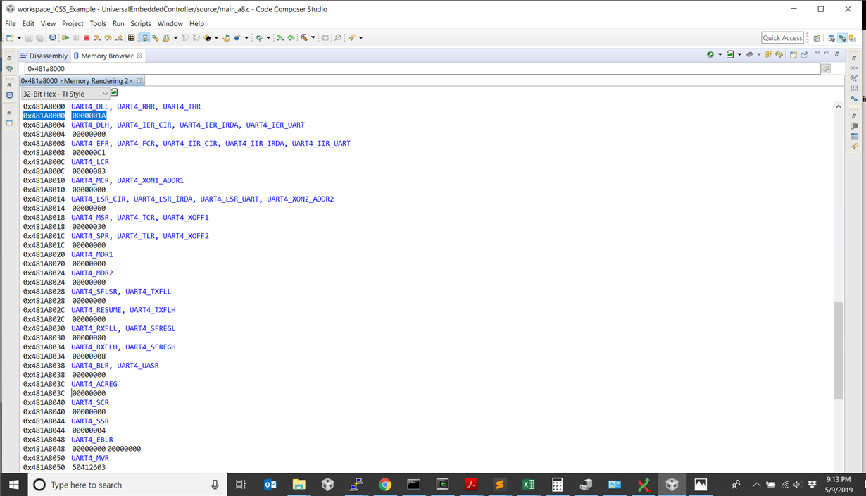
    That leaves the actual UART configuration as the likely issue. My first suspicion would be the baud rate itself. I recommend opening a CCS memory window to address 0x481A_8000 (UART 4 base address) and taking a screenshot. It's difficult to interpret these registers because many of the addresses are used for multiple different registers, i.e. depending on various mode bits as well as whether you are reading or writing the address.

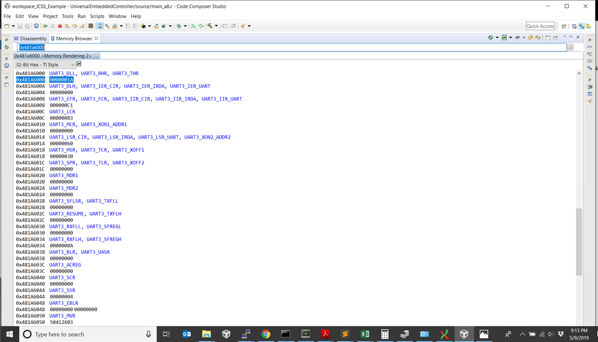
    Did you say that UART3 was working fine? You may want to get a similar screenshot there for comparison to see if anything is clearly different.
  • Thank you for this reply. I learned something, but the problem still remains. 

    I did also learn that in order to examine the Configuration Mode version of the register, I had to modify the UART_LCR[7] bit. After doing so I was able to take the following screenshots:

    See attached pictures. The Baud rate fields are configured identically, but the UARTn_RXFLL, UARTn_SFREGL and UARTn_RXFLH, UARTn_SFREGH registers do not match. This implies that the frame length setting is incorrect? All other fields are identical. Let me know if there is something else that I should investigate or try. 

    Thank you. 

  • Any additional input on this? I am stranded now without this UART functional which is critical to the project. I imagine my previous post helped clarify something?
  • Nicholas,

    Can you please confirm that you are using buadrate of 115.2 kbps or some other standard baud rate? Can you confirm BRad`s question on whether you have UART3 functional with the right baud rate ? How many UARTs are you enabling and is UART4 the default debug UART instance that is setup using board for STDIO operations.

    I noticed in your earlier code you are setting the driver to read and Write data in binary format and then you try to send character string out. Shouldn`t the driver DataMode be set to UART_DATA_TEXT. Also, please indicate if you have modified interrupt setup, clocking or modes of operation in UART_soc.c.

    Regards,
    Rahul
  • Rahul,

    Yes I am using a baud rate of 115.2k on both UART 3 and UART4. And UART3 has been working and continues to work flawlessly. I am using UART3 as my debug UART instance. UART4 is intended to communicate with a peripheral device.

    I have not modified anything in UART_soc.c.

    Thanks,
    N
  • Nicholas,

    Could you try and see if using just the UART4, you see the same issue. If that can`t be done then can you include UART_soc.c file in your application project and disable the DMA for instance 4 . Default DMA mode is TRUE, you can set that to false for UART4. This would confirm if the issue relates to DMA usage in the driver.

    Regards,
    Rahul