This thread has been locked.

If you have a related question, please click the "Ask a related question" button in the top right corner. The newly created question will be automatically linked to this question.

AM3715: HSUSB1 clock issue at boot time

Part Number: AM3715

Dears:

There is an issue during booting.

Sometimes HSUSB1_CLK signal will not have output signal. 

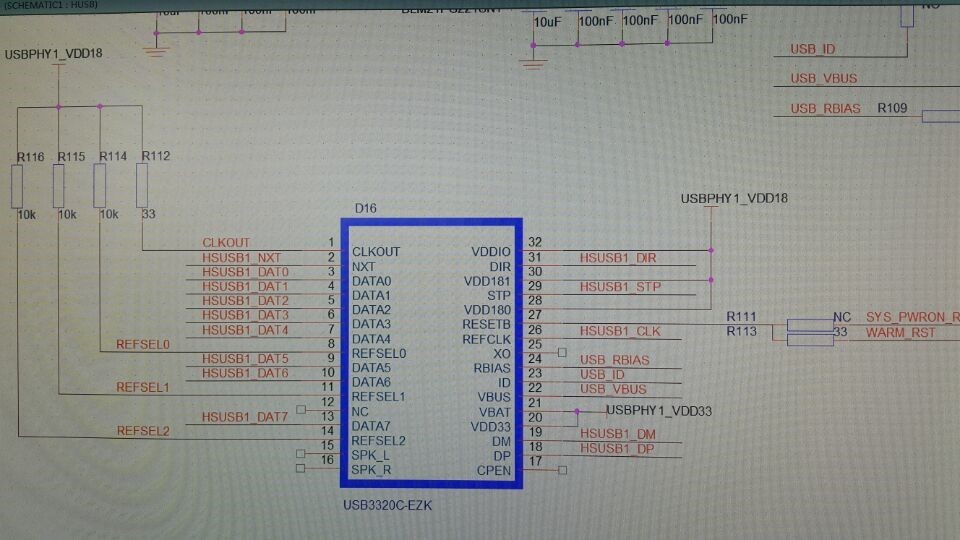
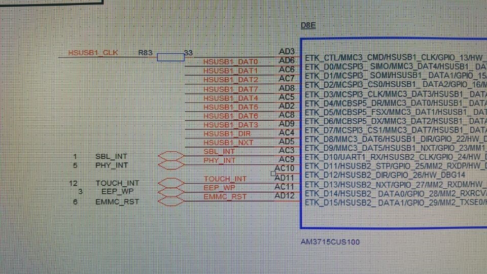
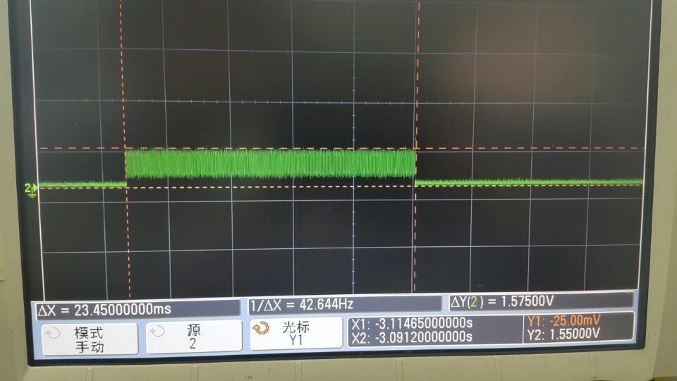
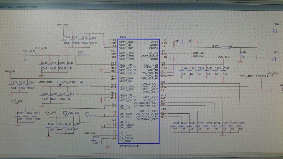
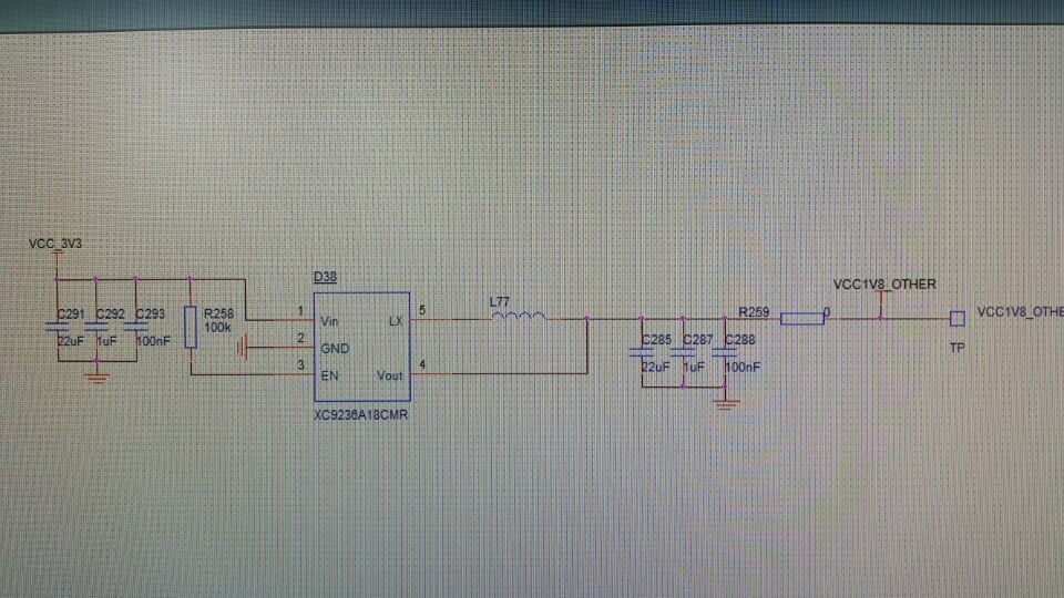
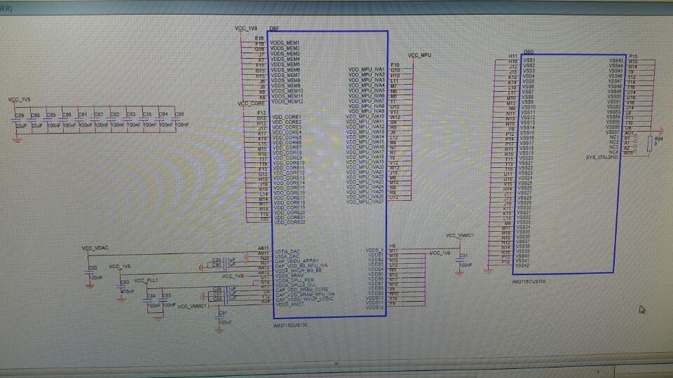
Pls. refer the below schematic and waveform.

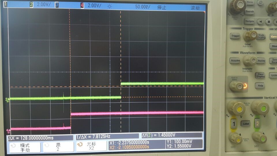
Btw, testing the delay time between sys_nreswarm and  1.8V is different with datasheet. 

The time is about from 115 to 133ms. The waveform as below picture:

Green line is sys_nreswarm, and red line is 1.8V.

Pls. give some advice about these issues.

  • Hi Luck Wu,

    Could you give details about software running on your board - which SDK and kernel version. If you have booting log or "dmesg" kernel log should be useful to attach it in a text file.
    About schematics I'll contact hardware expert for comment.

    Regards,
    Tsvetolin Shulev
  • Can you clarify your observations:

    -Do you see HSUSB1_CLK toggle on every boot? But sometimes it stops after 25ms?
    -Does HSUSB1_CLK never toggle on some boot up attempts?
    -What is the timing relationship between nreswarm and HSUSB1_CLK?
    -What is your boot sequence?

    Can you read register CONTROL_STATUS after each scenario (HSUSB1_CLK present, HSUSB1_CLK not present)?

    There is no timing relationship between 1.8V and nreswarm, other than nreswarm will rise sometime after 1.8V is stable. What delay time are you referring to?

    Regards,
    James
  • Hi James:

    Pls. refer the below information:

    1. Operating system: WCE6.0, using BSP_WINCE_ARM_A8_01_02_00. It will configure DPLL4 and DPLL5 for hsusb1_clk.

    2. Do you see HSUSB1_CLK toggle on every boot? But sometimes it stops after 25ms?

    Luck: Yes.

    3. Does HSUSB1_CLK never toggle on some boot up attempts?

    Luck: Yes. 

    4. What is the timing relationship between nreswarm and HSUSB1_CLK?

    Luck: After nreswarm changes high level HSUSB1_CLK will output clk.

    5. What is your boot sequence?

    Luck: about 12s.

    6. Can you read register CONTROL_STATUS after each scenario (HSUSB1_CLK present, HSUSB1_CLK not present)?

    Luck: Customer can not read it.

    7. There is no timing relationship between 1.8V and nreswarm, other than nreswarm will rise sometime after 1.8V is stable. What delay time are you referring to?

    Luck: Since the different boards the testing results are different.

    If there is any other query, pls. feel free to let me know!

  • Hi James:
    Could you kindly help to give some advice.
  • Hi Tsvetolin Shulev:
    Could you kindly help to give some advice.
    I know there is so fewer support about WINCE system.
    However, the issue happened during boot step, and not boot system.
    Pls. give some advice about it.
  • Hi James:
    Could you kindly help to give some advice.
    I know there is so fewer support about WINCE system.
    However, the issue happened during boot step, and not boot system.
    Pls. give some advice about it.
  • Luck,
    -Why can't the customer read CONTROL_STATUS register? Do the have JTAG access on the board? Do they have a debugger?
    -How many boards have they tested? How many boards are failing?
    -the scope shot you show of the clock is showing a voltage swing of only 1.5V. This indicates a power issue on the board. Have your customer check all voltage rails on the board for proper power sequencing and voltage levels.

    Regards,
    James
  • Dear James:

    Sorry for my delay reply, pls. refer the below information:

    -Why can't the customer read CONTROL_STATUS register? Do the have JTAG access on the board? Do they have a debugger?

    Luck: There is no JTAG on Customer's board, since the boards are in MP state.

              Is there any other method to test it?


    -How many boards have they tested? How many boards are failing?

    Luck:They have tested 80pcs boards, and there are 33pcs boars failling.


    -the scope shot you show of the clock is showing a voltage swing of only 1.5V. This indicates a power issue on the board. Have your customer check all voltage rails on the board for proper power sequencing and voltage levels.

    Luck:pls. refer the below pictures:

    Pls. give some advice about it.

  • Luck, have they ruled out an assembly issue on the non-working boards?  Can they try to perform a processor swap (move a good processor to a bad board, and move a bad processor to a good board).  Or simply put a new processor device on a bad board.

    They also need to check the voltage rails you show to ensure proper voltage on all the rails.  

    Regards,

    james

  • Hi James:

    Pls. refer the below information:

    Luck, have they ruled out an assembly issue on the non-working boards?  Can they try to perform a processor swap (move a good processor to a bad board, and move a bad processor to a good board).  Or simply put a new processor device on a bad board.

    Luck: Yes, the customer performed the processor swap which is putting a new processor device on bad board.

              And found only parts of the bad boards are OK, and there are some boards are bad.

    They also need to check the voltage rails you show to ensure proper voltage on all the rails.  

    Luck:Customer confirmed they use PMIC and the voltages are ok.

    BTW, before you concerned about the below issue:

    -the scope shot you show of the clock is showing a voltage swing of only 1.5V. This indicates a power issue on the board. Have your customer check all voltage rails on the board for proper power sequencing and voltage levels.

    I have a question, and how is the voltage level  of the requirement? since customer compared bad board and good board the voltages all about 1.5V.

    Pls. kindly help give some advice about it.

  • Luck, i'm confused by your response.  When they put the new processor on the bad board, did the board work or not?

    Technically, Voh is 1.35V, so the high voltage on the clock is technically within a valid range, but that's just one measurement on one board.  The voltage may be worse on other boards.  Regardless, 1.5V still indicates a possible problem.  The high voltage should be closer to 1.8V.  

    Regards,

    James