This thread has been locked.

If you have a related question, please click the "Ask a related question" button in the top right corner. The newly created question will be automatically linked to this question.

WiLink™ 8 Module 2.4 GHz WiFi® + Bluetooth® COM8 Evaluation Module (WL1835MODCOM8B) & AM335x Evaluation Module (TMDXEVM3358)

Other Parts Discussed in Thread: TMDXEVM3358, WL1835MODCOM8B, WL18XXCOM82SDMMC

Dear All,

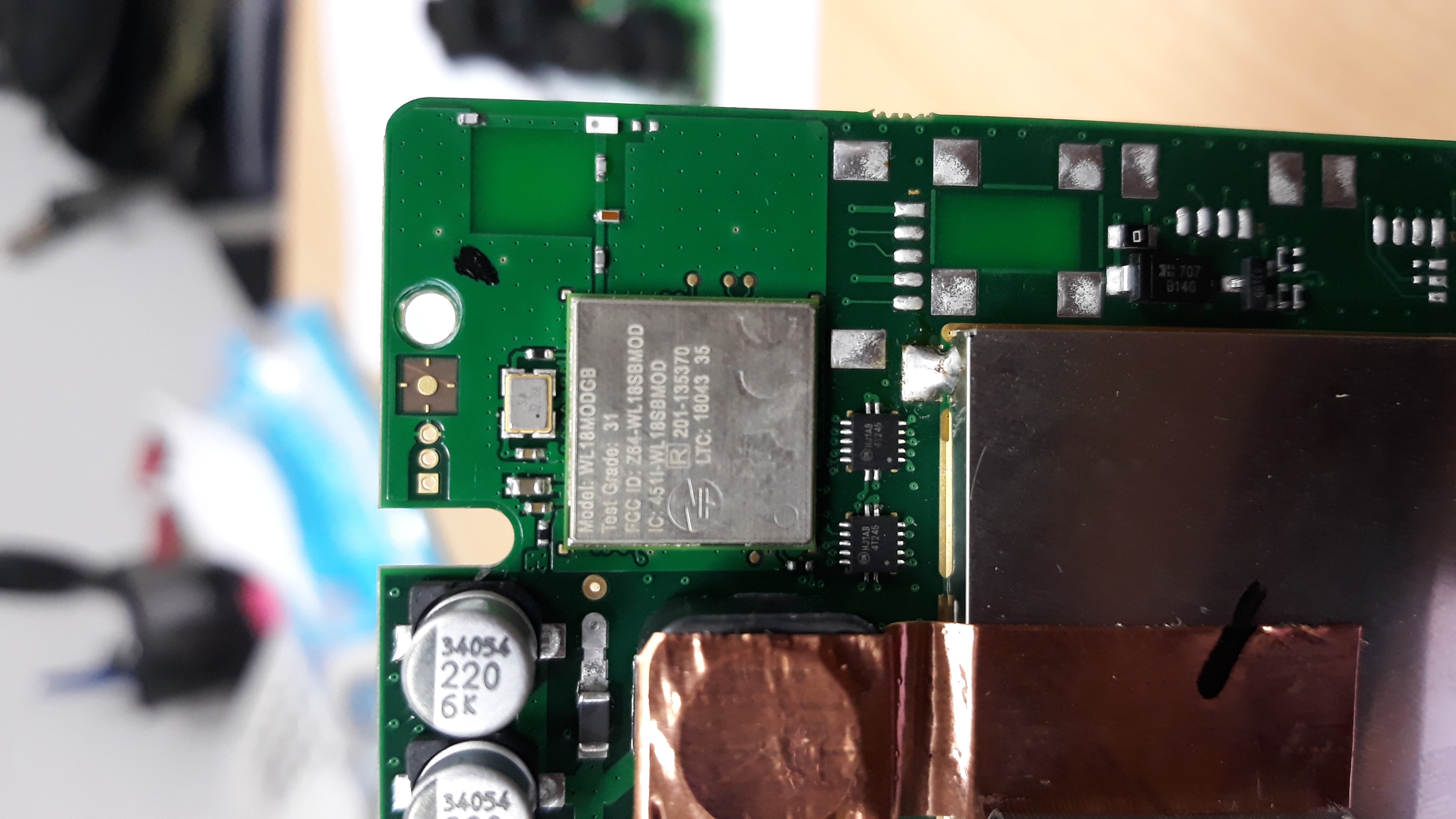
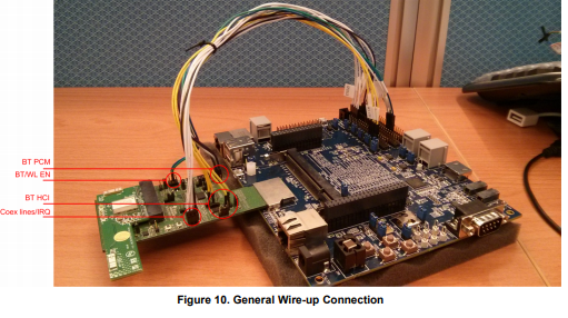
Now, we currently used Wifi module "WL18MODGB" for one of our products as attached.

And, we need to test that WIFI nodules on board by using PXA Signal Analyzer (N9030A) at our laboratory in Indonesia due to some reasons Do you have solution how to testing that WIFI module? And, what kind of parts which required to perform that test? 

Your kindly assistance would be appreciate related this matter.

Thank you. 

  • Hi Dimas,

    Dimas Andy Kurniawan said:
    we need to test that WIFI nodules on board by using PXA Signal Analyzer (N9030A) at our laboratory

    Can you please provide more details on exactly what tests are you about to perform? Do those tests required conducted or radiated measurement?

    Best regards,

    Vihang

  • Hi Vihang,

    Thanks for your reply. We need to perform RF test with do some procedures below,

    1. Due to our product specification, channel will set automatically between 1 to 13. So, we need to find the way how to select into specific channel. 
    2. We need to change transmission rate (b/g/n/MIMO).
    3. We confused due there is no connector for connecting PXA Signal Analyzer with our PCB. They using cable + connector as attached.

    And my questions as below,

    1. How to connecting WiFi module with their PXA Signal Analyzer using connector as attached?
    2. Would you give recommendation of parts/software that required to perform this test?
    3. It possible or not if we buy WL1835MODCOM8B and TMDXEVM3358 for this testing purpose?

    Please kindly advise regarding this matter. Thank You.

  • Dear Vihang,

    ----------------Quoted-----------------

    Thanks for your reply. We need to perform RF test with do some procedures below,

    1. Due to our product specification, channel will set automatically between 1 to 13. So, we need to find the way how to select into specific channel.
    2. We need to change transmission rate (b/g/n/MIMO).
    3. We confused due there is no connector for connecting PXA Signal Analyzer with our PCB. They using cable + connector as attached.

    And my questions as below,

    1. How to connecting WiFi module with their PXA Signal Analyzer using connector as attached?
    2. Would you give recommendation of parts/software that required to perform this test?
    3. It possible or not if we buy WL1835MODCOM8B and TMDXEVM3358 for this testing purpose?

    --------------------------------------------

    Please kindly advise about this matter.  Your suggestion would be appreciated. Or, do you have another solution with whom i can make a contact with technical support from Texas Instrument? Due to we need to solve that in a short time. Thank You.

    Best Regards,

    Dimas

  • Hi Dimas,

    I hope all is well. There are 2 tools that we have available that you can do the required test (setting modulation and channels).

    1) IF you have pulled out RS232 and have a pull up resistor on the IRQ line you can used RTTT to do the tests. This is a GUI based interface that allows you to control the radio and does not require the host. In this way you can set the radio as you need. You can download this tool here:

    2) The other method is with the host and uses calibrator as part of the Linux system. IN this way you send calibrator commands over the SDIO buss so that you can control the radio. The calibrator commands to use can be found here:

    No for connection to the PXA. To do this you need to remove your first series component out of the module then solder on an RF pigtail such as the one below:

    The open end would be connect to the pad closest to the module. The other pad that you removed the series component from would be left open. In this way you have disconnected the antenna from the circuit and are sending the signal to the RF cable that you can then connect to the PXA. Note that you will also need to ground the outer cable shielding to ground on your board, thus completing the circuit.

    I hope this helps.

    Thanks,

    Riz

  • Dear Rizwan Murji,

    Thanks for your reply. So, we only need to buy WL1835MODCOM8B and TMDXEVM3358 from TI. After that, we conduct this test using PXA Analyzer with follow as your suggestion? Due to we cant do anything because to risky for our PCB unit.

    Awaiting your soonest reply.

    Best regards,

    Dimas

  • Hi Dimas,

    You need to discuss with your test house if that is an option for your product. Our module is already certified so you should be able to leverage the results of our modular certification. Note that for all product you still need to ensure that at the product level that you meet the radiated and spurious requirements as this is done at the platform level. This is done radiated so there is no need to have a physical connection and is not done on the TI HW.

    I hope this helps.

    Thanks,
    Riz
  • Dear Riz,

    Well noted for your answers. Which one have you recommended to conduct test that i was mentioned before,

    1. Using WL1835MODCOM8B and TMDXEVM3358. Or,
    2. Using WL18XXCOM82SDMMC and WL1835MODCOM8B and host platform. Which host platform we need to prepare?

    Option No.1 : WL1835MODCOM8B and TMDXEVM3358

    And which able to connect with PXA Analyzer using RF cable as below,


    Option No.2 : WL18XXCOM82SDMMC and WL1835MODCOM8B and host platform. But, where we can connect with our RF Cable with PXA? What kind of host platform that we need to prepare

    Please kindly advise above matter. Thank You.

    Best Regards, 

    Dimas Andy Kurniawan

  • Dear Riz,

    Any update regarding my question that i was sent to you?

    Best Regards,

    Dimas

  • Hi Dimas,

    The option I would recommend would be option 1 with the AM335. In this case the ANT1 is the primary antenna. If you look at the board you can see there is a U.FL connector. You can move the resistor that goes to the antenna to the path of the U.FL connector. In this way you can then use a U.FL to SMA cable to connect to the PXA.

    I hope this helps.

    Thanks,
    Riz
  • Hi Dimas,

    I am going to go ahead and close out this issue. If you are still having issues, please feel free to re-open or if the thread is locked, post again.

    Thanks,
    Riz