A related question is a question created from another question. When the related question is created, it will be automatically linked to the original question.
If you have a related question, please click the "Ask a related question" button in the top right corner. The newly created question will be automatically linked to this question.
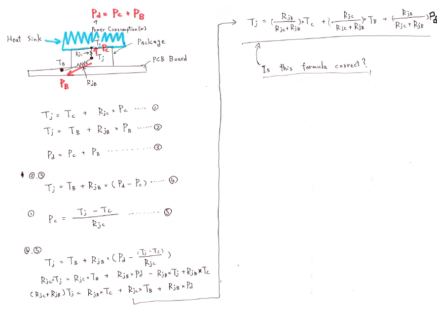
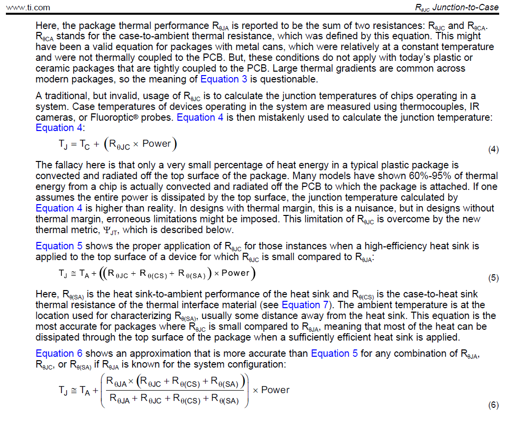
spra953c says that Equation 4 is invaild.
Because, a very small percentage of heat energy in a typical plastic package is convected and radiated off the top surface of the package.
so, I deduced the equation with the idea of two-resistance model.
The ADC32RF80 is a QFN package with a thermal ground pad. Most of the heat is intended to be dissipated through the ground pad to the board. A heat sink on the bottom of the board improves the performance; this is implemented on the EVM and on the TSW40RF80 reference design.
The picture above depicts adding a heat sink on the top of the device. Whereas adding a heat sink on top can't hurt thermally, it would be much more effective on the bottom. The app note references that dissipation to the top (i.e. case) is not accurate since most of the heat is not dissipated there.
I have an issue with designating different power dissipations: Pd, Pc. The power dissipation of the device is fixed for a given set-up conditions. That power will be dissipated in one way or the other, through board and case. Given that the dissipation through case is limited, using the board is more accurate. I would focus on using the theta-jB parameters for the thermal calculations. If a heat sink is used on the bottom, conceivably, the additional theta-bs (board to sink) and theta-sa (sink to ambient) could be used similar to equation 6.
If the goal is to determine junction temperature and you know the power dissipation of the device and you can measure the board temp, then I think that you can use the standard theta-jb equations.