This thread has been locked.

If you have a related question, please click the "Ask a related question" button in the top right corner. The newly created question will be automatically linked to this question.

TSW38J84EVM: TRF3722 parazitic AM modulation

Part Number: TSW38J84EVM


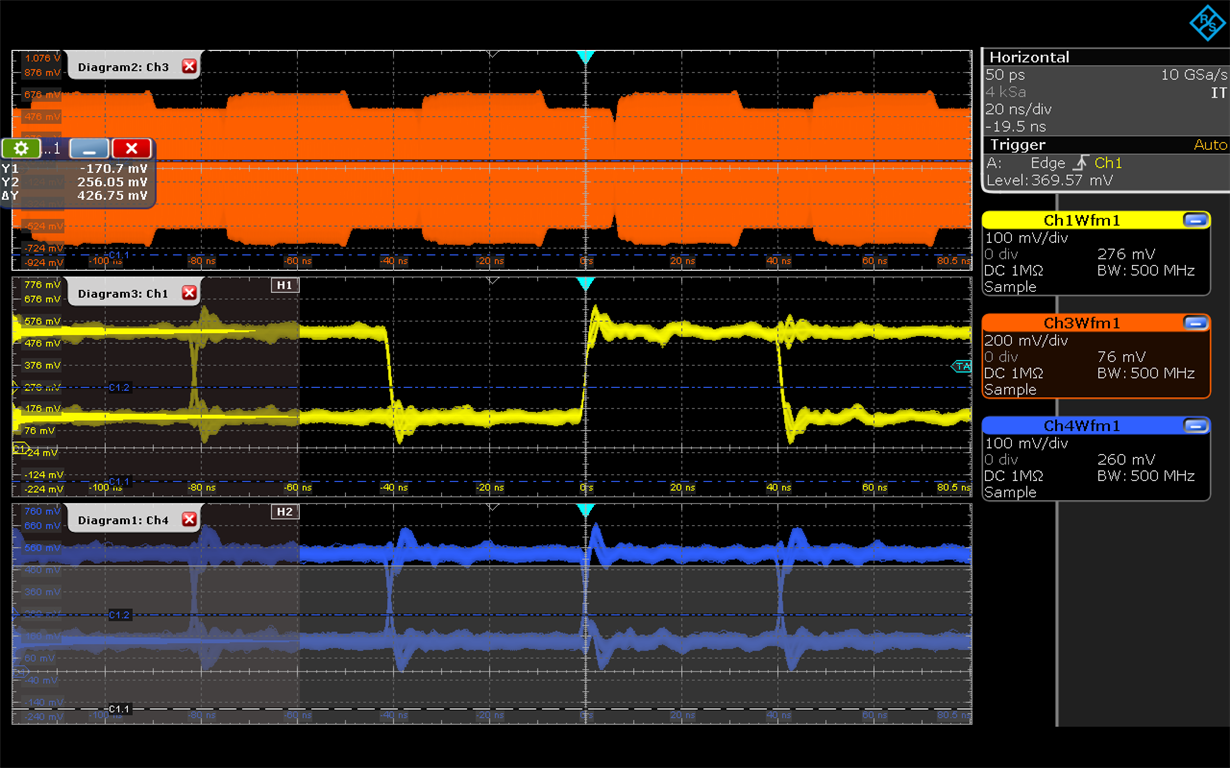
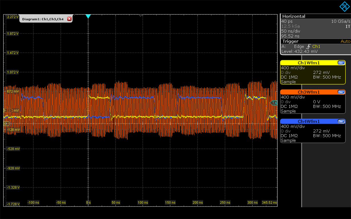
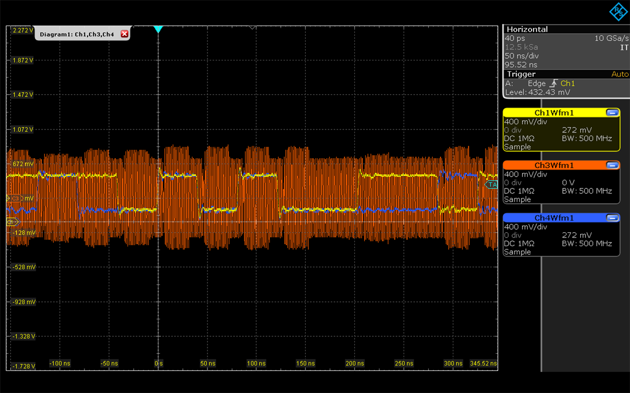
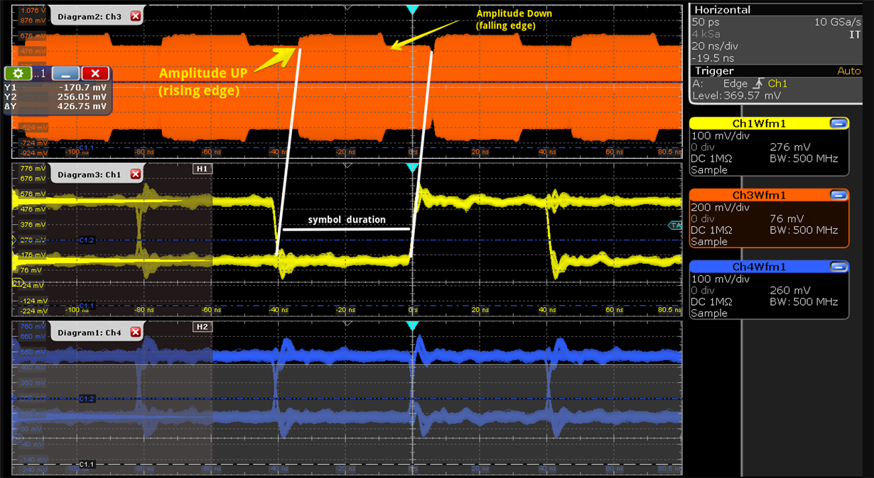
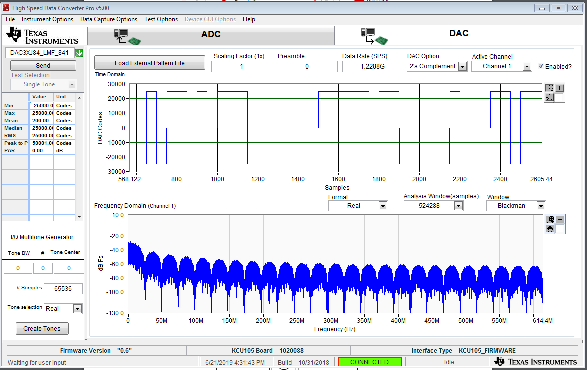
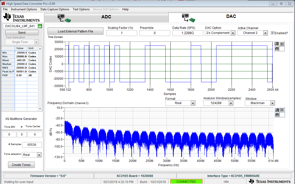
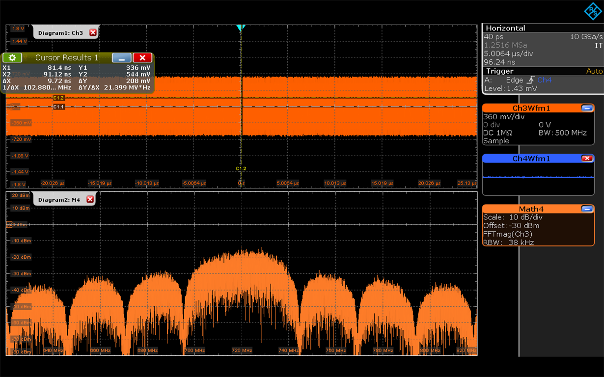
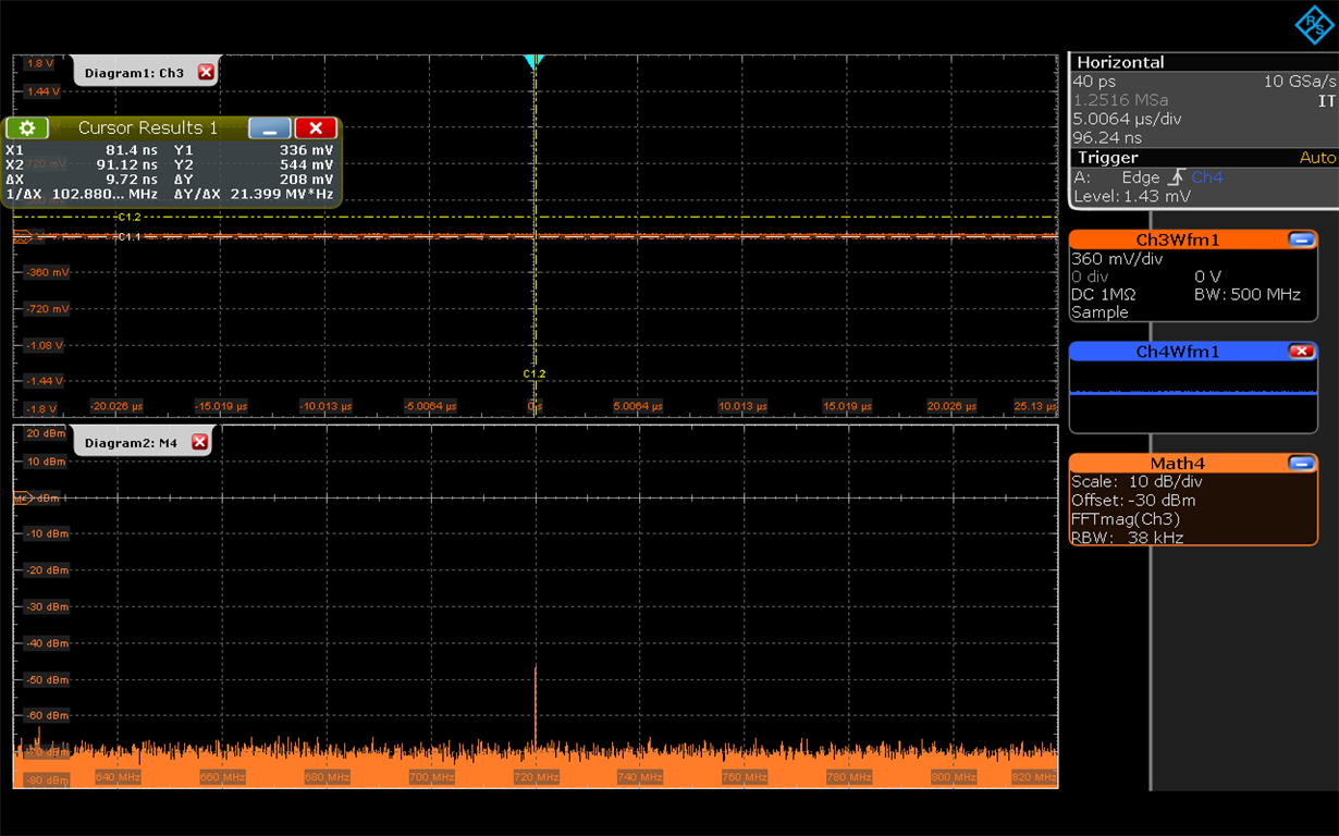
We work with the TSW38J34 board. At the output of the modulator TRF3722 you can see the changes in signal amplitude. At the input of the modulator (I and Q) QPSK modulation signal. There is no amplitude distortion at the input of the modulator. What could be the problem?

  • The same situation for TRF3705 on TSW38J84

  • Andrey,

    I am sorry, I am not exactly sure how to interpret your result and also interpret the problem. If you can highlight the problem with indicators and arrows (perhaps in a power point or word document attachment) to explain your concerns, I would greatly appreciate it. 

    My brief understanding (with lots of assumptions) is that your low level signal at I/Q result to some amplitude in modulator output. I would say this is due to the nature of quadrature mixing where there could be some LO leakage at around -40dBc of default suppression. You can perhaps look at the spectrum analyzer to see if you observe some sort of LO leakage directly at the LO frequency. Then, correlate this result to the time domain plot.

    -Kang

  • Then I send to modulator only I or Q (another quadrant is 0) the picture 1 is same (amplitude RF signal is changed in symblol time). 

  • Hi,

    I think this has primarily has to do with the quadrature mixing of the TRF3705 and TRF3722. Keep in mind the I is modulated with Cosine(2*pi*LO) while Q is modulated with Sine(2*pi*LO). The sine/cosine has exactly 90degree phase shift, which explains that the waveform is different 1/2 the time, this is basically the cosine/sine transition happens.

    If both I+Q = full-scale at all 1s, you will get 3dB more the amplitude. You can give it a try, or use Matlab model to help you analyze the time domain expected waveform.

    Matlab Code

    close all;

    clear all;

    %% definitions

    % the following section defines the sampling frequency and fft size for the

    % entire transceiver design.

    % define sampling frequency

    fs = 1000;

    % define FFT size

    N = 1000;

    % define number of samples

    n = 1:N;

    % complex bin size = n/fs instead of n/(2fs)

    fft_bin_size = fs/N

    % fft x-axis

    bin = -fs/2:fft_bin_size:fs/2-fft_bin_size;

    %% baseband model.

    % defines the baseband frequency and introduce baseband analog higher order

    % distortion gain in both quadrature and real paths.

    fb = 100; %define baseband frequency

    flo = 300; %define LO frequency

    i_in = cos(2*pi*fb/fs*n);

    q_in = sin(2*pi*fb/fs*n);

    bb_in = a1*i_in + a1*j*q_in;

    %calculate the energy of baseband signal for normalization.

    energy_bb_in = bb_in*bb_in';

    % convert time sample into frequency samples via Matlab's FFT function

    BB_IN = fft(bb_in);

    % plotting the ideal baseband signal after modulation and demodulation

    % note: the operation of BB_IN/sqrt(N) is to ensure energy calculation of

    % time domain and frequency domain are conserved. I.e. Parseval identity.

    % 10*log10(energy_bb_in) is used to normalize the result to 0dB.


  • Thank you all, problem solved. The problem was in the load output of the modulator. The load was 1 megohm instead of 50 ohms.