This thread has been locked.

If you have a related question, please click the "Ask a related question" button in the top right corner. The newly created question will be automatically linked to this question.

CCS/ADC32RF80: Is there any reference code?

Part Number: ADC32RF80
Other Parts Discussed in Thread: ADC32RF45EVM, LMX2582, ADC32RF45

Tool/software: Code Composer Studio

Hi TI

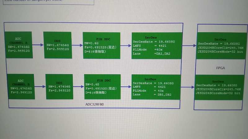
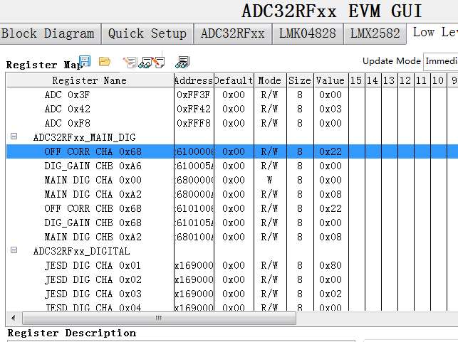
We want to develop ADC32RF80, but there are too many registers.           

Is there any reference code that can help us?           

Can it be provided?           

Thanks.

Jerry

  • The start-up sequence (9.1.1) in the device datasheet (http://www.ti.com/lit/ds/symlink/adc32rf80.pdf) explains the steps to configure the device and referes to a folder (SBAA226). This folder contains the configuration files associated with the steps in the sequence. This should help you with the required register writes to configure the device in a specific mode.

    Regards,

    satish.

  • Jerry:  Is there a question/issue from your previous post?  I do not follow it.  --RJH

  • Hi RJH

    Sorry, my questions is as follows.

    Can you help provide the following register configuration?

    Thank you.

    Jerry

  • Jerry:

    From the picture I ascertained your requirement:

    • Fs = 2949.12 MSPS
    • fdata = 491.52 MSPS
    • Dec = 6
    • LMFS = 4421

    I do not agree with the serdes speed of 19.6608 Gbps as that is too fast for the device.  Per the datasheet the mode corresponds to the one copied above.

    You can use the ADC32RFxx GUI to test this mode and/or to download a configuration file.  If you do not have the GUI, you can download it from the ADC32RF45EVM product page on TI.com.

    When you first open the GUI you can go to the Quick Setup tab.  Change the "Select the Device" menu to "ADC32RFxx".  Then follow this sequence:

    • Change "Clock Source to ADC" to "LMX2582 to ADC" or equivalent
    • Change "ADC32RF45 Mode" to "DDC"
    • Change "Internal Clk Freq" to 2949.12
    • Uncheck "Dual Band"
    • Change "Decim Factor" to 6
    • Change "PLL Mode" to 40x

    The program should auto-populate the LMFS 4421 configuration.  From there you press "Program EVM".  This will generate a config file that you can copy for your own system.  For example, you can double-click the "Idle" name in the lower left window to open the status log where you can see all of the register writes happening.

    --RJH

  • Hi RJH,

    Thank you for your kindly support.           

    I would like to ask the following table which contains all the register configurations of the clock chip and ADC.

    I want to know if the chip can work properly if it is configurated in the order of tables in the process of configuring the chip.

    Regards,

    Jerry

  • No.  There is an order required which the log file/config file supports.  --RJH

  • But the configuration file is a copy of the form.There are many clock operations and status reads in the log file.I want a complete and concise configuration sequence that can be used for my own project.

  • I am a bit confused.  The Low Level Tab displays the register address and data for the LMK clock chip and the ADC chip in a compartmentalized fashion to make it easy to read and understand.  It is not possible to simply regurgitate the address/data from the low level page and get the device working.  There is a proper sequence needed to establish the JESD link.  Actions like turning on and off the LMK sysref are required actions to get the link established. There may also be some proprietary registers that are written for ADC trimming purposes that are not specifically called out in the Low Level Tab.

    The GUI outputs a config file consistent with the mode of operation set-up from the front panel.  This config file is intended for you to use in your project.  The idea is that if it works for the EVM then it will work for your system.  Of course, you may need to make minor modifications to support your product like changing the clock output ports to support your unique layout.  The file is long and may seem like it is not optimized.  There likely is some repetition that could be streamlined a bit, particularly related to opening and closing SPI pages.  But for simplicity this level of optimization is not implemented in the config file.

    --RJH