This thread has been locked.

If you have a related question, please click the "Ask a related question" button in the top right corner. The newly created question will be automatically linked to this question.

TSW 3725 configuration

Other Parts Discussed in Thread: TSW3725, CDCE72010

Hello,

I have read that there are two ways of configuring the TSW:

 - Matlab GUI (Standalone mode).

 - tswconfig (SCBP mode).

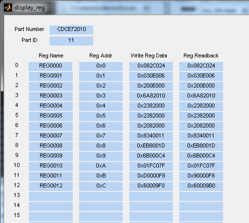
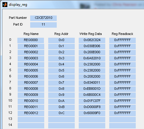
I have noticed that if Iconnect the TSW output to a spectrum analyser, a tone appears in the selected LO frequency. However, this only happens when using the Matlab GUI, when we try to use the tswconfig application, nothing happens. It seems that the tswconfig application is not doing anything.

Why could this happen?

Thank you.

  • By the way, I am using Azcom's SCBP with TSW3725 and this is what I am getting when programming the TSW:

     - Programing in standalone mode (D11 blinking, Matlab GUI): I get D4 and D5 on, but D3 off

     - Programing in SCBP mode (D14 blinking, tswconfig): D3, D4, D5 off (nothing happens).

    It seems that something is wrong. Can anyone help me?

    Thank you in advance.

    Regards,

    Oscar

  • Hello Oscar,

    D3 will tell you if the CDCE72010 chip is locked or not.  THe CDCE72010 sends clock signal to two TRF3720's.  If these TRF3720's lock than D4 & D5 will light up.  So if the CDCE72010 chips is not locking (D3), than there is a chance D4 and D5 may not.  So lets concentrate on D3.

    Can you verify the following for me

    -   Does the CDCE72010 readback the correct information when the DISPLAY button is selected?
    -   Can you measure the reference input frequency/power at R370 (0 ohm resistor near pin 59 of CDCE72010 device).  There should be a 30.72M signal present.
    -   Verify you have 3.3V at the 3.3V_CDC_VCC test point (exposed gold area - labeled with silk screen)
    -   What serial number are you having this problem with?

    When you are measuring the board in stand alone mode, is it connected to the SCBP at that time? 

    Thanks
    Chris

  • Hello Chris,

    I have checked the registers' values and they seem to be OK, although the write and readback data is not exactly the same in some cases:

    However, in SCBP mode using the tswconfig, this values are not written:

    • I have measured the input frquency at R370 and is righ (30.72 MHz).
    • The voltage at CDC_VCC test point is correct (3.3V).
    • The serial number is: SN49

    So, as a summary, I have checked what you told me and looks fine. The tswconfig command does nothing. The Matlab GUI lits on leds D4 and D5, but not D3.

    Then:

    1) What do we need in order to use the tswconfig command? Is it compatible with Azcom's SCBP?

    2) I have noticed that D2 LED (CDC_STATUS) is ON after booting, but it switches OFF after configuring the TSW. Is this normal?

    3) How do I continue?

    Thanks,

    Oscar.

  •  

    Hello Guillermo,

    Thanks for all the information.  First I would like to describe some of the differences and functionality, and then after that maybe we can think best how to proceeed.

    In stand alone mode, register 11 and register 12 read different values for write and read data.  The difference seen in register 11 (D0000F8 vs 90000F8) is expected and is of no concern.  D=1100, and 9=1000, the 2nd bit is a read only bit used to confirm if the CDCE72010 EEPROM is locked.  We do not use the CDCE72010 EEPROM with the TSW3725 and there for the EEPROM is unlock and should read a 0. 

    The difference seen in register 12 (60009F0 vs 60009B0) is the problem we are chasing.  F=1111, and B=1011, the 2nd bit is used to read if the CDCE72010 PLL is locked or not.  This bit has the same functionality as LED D3.  When D3 is on this bit should be a 1 and when D3 is off it should read 0. 

    In SCBP mode, it looks like you are not able to readback.  When SW2 is in SCBP mode readback through the USB is disabled.  Using switch 2, It maybe possible to program the TSW3725 in SCBP mode and then switch back to stand alone mode for readback.  This would probably be a good thing to try.

    1) What do we need in order to use the tswconfig command? Is it compatible with Azcom's SCBP?
    The DSP or Azcom team will need to answer this question.  This command has something to do with how the SCBP programs the TSW3725.  I'm not terribly knowledable about this command.  The TSW3725 just responds to what it is given from the SCBP.

    2) I have noticed that D2 LED (CDC_STATUS) is ON after booting, but it switches OFF after configuring the TSW. Is this normal?
    D2 should be on. In stand alone mode, this would imply that the CDCE72010 device does not see a  reference signal.  This is confusing as you said you saw the 30.72M signal at the resistor near the device.  However, this could explain why D3 and Reg 12 are saying the CDCE72010 is not locked.   I can reproduce this behavior on my board if the 30.72M signal amplitude is less <2V at R370.  If the signal is 2V or greater than D2 and D3 turn on.

    3) How do I continue?
    Great question, you've confirmed the CDCE72010 can readback, it is creating divided signals from the on board VCXO (D4 and D5 would not light up if it wasn't),  we confirmed D3 and reg 12 are telling us the same thing, and you've confirmed that the reference signal is making it to resister R370.  SN49 passed when it was in Dallas being tested.
    A) The only thing I can think of at this point is that the 30.72M reference clock amplitude maybe too small.  Can you measure its amplitude?
    If it is too small I know there is a resistor on the SCBP that can be added or removed to correct this amplitude issue.

    B) If 3A does not fix this then, do you have the ability to try a different SCBP with the TSW3725 and see if the TSW3725 works with it?

    Chris

  • Hello Chris,

    Thanks to your help I have finally been able to fix this problem, and now both LEDs (D3 and D2) are lit after configuring the TSW. I can also configure the board in both standalone and SCBP mode (Matlab GUI and tswconfig command).

    The new issue is that, after configuring the TSW, the GC5330 should be activated. To do so, there is a program in the filesystem (gc5330hostapp) and a startup script. However, when we execute it, the following error appears:

    Issue DPD_TGTCFG write.
    Total errors for the command: 1
    _____________________________
    28.311: L1 E=37 at 16
    sDPD_TGTCFG_WR failed with status -1.
    Load GC configuration error!$summer_gainw 1 1 -6
    #cfr_gainw 1 1 2 -6
    $summer_mapw 1 0 0x1
    $summer_mapw 1 1 0

    It seems that the GC5330 clock is not present. To correct this, it is necessary to set a CPRI LINK (4x 2.4Mb/s). I found an example code (aif2LteTesProject) that apparently does that. However, I don't know if it is running the example just work, or it is necessary to pause the execution in the middle so the link remains up, or something needs to be changed.

    ¿Can you help me with this?

    Thank you.

    Oscar.

  • Hello Oscar,

    These questions now are falling outside of my knowledge base.  I believe the questions asked now fall under Azcom's responsibilities.  If you do not have their contact information you can email this address  sales@azcom.it . 

    Let me know if they agree with this.  I have sent them your latest set of questions. 

    Thanks

    Chris


  • Hi all,

    Please note that we have now published a software package that helps with the setup and operation of the SCBP+TSW3725 combo:

    Best Regards, Laurent.
  • Is the SCBP + TSW3725 package still supported? We have acquired both platforms, but there seems to be no support for the TSW3725 aside from the package above. Is the standalone GUI still available (TSW3725 GUI and MCR INSTALLER.zip)? 

    I am trying to run the LTE single tone example as described in the readme. Seems I am stuck with init buttons disabled due to CPRI link disabled?

    Is help still available for this package pair?

    FPGA Revision 102a LTE 20 MHz Firmware
    External 10 Mhz clock 000f 10 MHz clock detected and configured
    SFP AIF Config e0e0 SFP not connected but configured
    Ouput RF Board 0001 TSW3725 is configured
    CPRI Link Status 0001 DSP-FPGA CPRI link is not ready
    GC5330 Sync_A 0000 GC5330 is not configured
    TX1 Scaling by FPGA 0000 No radio output on TX1
    TX2 Scaling by FPGA 0000 No radio ouput on TX2