I am integrating a 4DSP FMC30RF card into my design. To my understanding, this board was designed for TI as a card for demonstrating multiple TI chips. We are having some technical problems that they suggested would be better answered by TI. I am copying posts that I previously posted in a 4DSP forum.
The board uses the following TI components:
Main Clock generation: CDCE62005
LO PLL: TRF3765
IQ Downconverter: TRF371125
AFE: AFE7225
The CDCE62005 is generating 122.88 MHz clocks using from an external 10 MHz atomic reference. The TRF3765 is configured for 1575.420 MHz for baseband downconversion of a 1575.420 MHz signal. The TRF371125 is configured with filter bypass off, but with maximum filter bandwidth. The AFE7225 is configured with an input clock divider of 1 but with internal decimation enabled for a final sampling rate of 61.44 MHz. I am executing automatic calibration of the AFE.
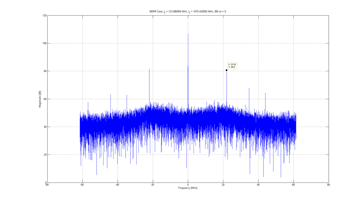
In this configuration, I see spurs at +/- 22.02 MHz at about 30 dB above the noise floor. This frequency is an alias of the LO at 61.44 MHz sampling. I believe that the signal is appearing AFTER the filter in the IQ downconverter because I am unable to suppress the tones by decreasing the filter bandwidth. I confirmed that our filter configuration is taking effect because I was able to configure the filter to suppress a tone at LO minus 20 MHz that appears adjacent to the aliases. To me, it looks like the LO is coupling into the analog I and Q channels prior to entering the AFE.
If I disable the AFE's decimation for an effective sampling rate of 122.88 MHz, I am able to observe aliases of at least the first 4 harmonics of the LO. What could be going on here?
Even worse, if I apply a tone at 2 MHz above the LO, I get an image 2 MHz below the IF as well. Could this be due to an IQ imbalance or problems in calibration?
For what it's worth, I am mostly an embedded software engineer and not an RF expert. It's possible that I overlooked something basic. However, I have been able to replicate some of this behavior with 4DSP's reference design as well.
I have attached a plot of the spectrum of the baseband data with a 1575.420 MHz LO and 122.88 MHz sampling (no decimation in the AFE).
Let me know if you need any additional information.
Thanks,
Jeff


