This thread has been locked.

If you have a related question, please click the "Ask a related question" button in the top right corner. The newly created question will be automatically linked to this question.

URGENT: getting started with LMX2492EVM, no output

Other Parts Discussed in Thread: LMX2492, LMX2492EVM, CODELOADER, USB2ANY

Hello,

I have recently purchased following LMX2492 evaluation board from TI, and want to get going with it quickly.

I am thoroughly following this user guide and the youtube video.

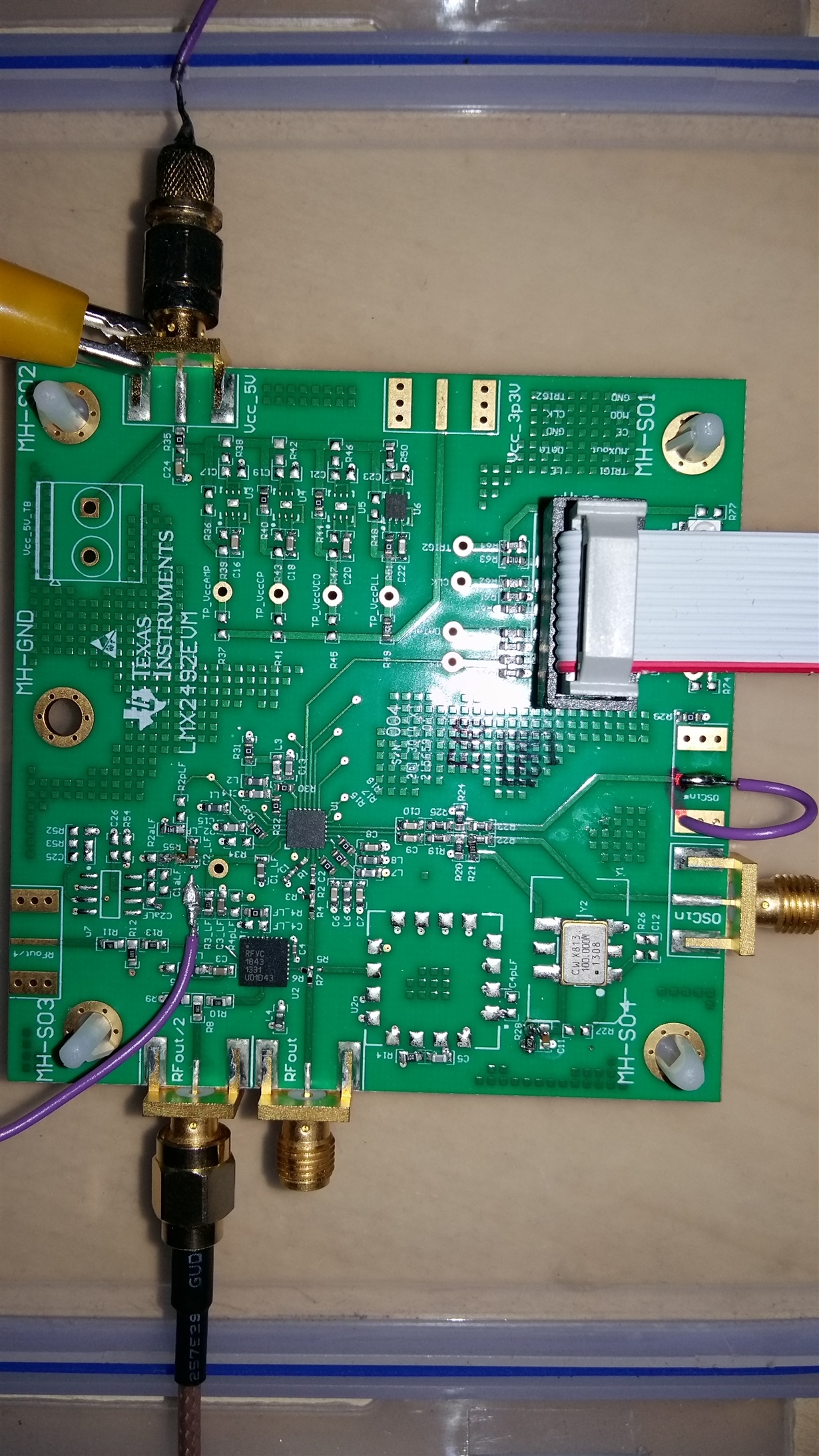
I couldn't figure out what is the Red-Probe in the video. But by close watch, it seems to be supply to Trig1, so I connected Trig1 to 5V. As per guide, this is not required, but I imagined it could be trigger. After all possible efforts,  I couldn't make it work. I don't see any output on oscilloscope. Even if my oscilloscope is not able to sample directly at RF frequency (samples upto 1 GPS ),  I believe I should see some output atleast.I am using CodeLoader for programming it as described.

Best Regards,

Babu Devnarayan

  • Hi Babu,

    Please look at this post:

    By default, it doesn't seem the on-board XO is receiving power. Without the on-board XO you will not get an output.

    Please populate the resistors R21 and R28 with the values indicated on the User's Guide Schematic, to power the XO.

    The red probe seems to be connected to TRIG1 Test point.

    Best Regards,

    Julian

    If my post answers your question, please click on "Verify Answer" button.

  • Hi Julian,

    Thanks a lot...I have soldered SMD resisters R21 = 18ohm and R28 = 10ohm, and oscillator seems to be up now as I can see 100MHz output from Oscin Pin. However, still I don't see any output on RFout, RFout/2 or RFout/4 except some apparent noise. 

    What's missing ?

    I am using this oscilloscope -Picotech 5444B

    https://www.picotech.com/oscilloscope/5000/flexible-resolution-oscilloscope

  • Hi Babu,

    When you pre Ctrl+L to program the device, do you see a small change in current coming from the power supply? if so it's likely that the device is being programmed.

    Also did you set your scope termination to 50 ohm?

    Thanks,

    Julian

    If my post answers your question, please click on "Verify Answer" button.

  • Hi Babu,

    Also please provide a screenshot of the PLL tab settings in code loader and the bits/pins tab. Please go to the registers tab please export the register settings into a text file and attach it.

    Thanks,

    Julian

    If my post answers your question, please click on "Verify Answer" button.

  • Hi Julian,

    Thanks a lot. I have left office before your message arrived...so I will try your suggestions tomorrow. Can we do a Skype tomorrow to sort this out, because I have wasted whole day on this...and thinking of waiting for 1 more day for this is killing me due to time constraint.

    Best Regards,

    Babu
  • Does your scope have enough bandwidth for this?

    By default RFout/4 is turned off. Look at the schematic on the LMX2492 User's guide. Switch L5p to l5 to enable it.

    In default code loader settings VCO frequency is 9600 MHz. So RFout=9600MHz and RFout/2=4800MHz.

    Again, just provide your code loader configuration tomorrow.

    Thanks,

    Julian

  • Hi Julian,

    My scope picotech 5444B got 200 MHz bandwidth with max 1GSPS (10 GSPS in ETS mode).

    Even if it does not have enough bandwidth to capture the signal...it should show some distorted signal, which should change when changing PLL settings....but right now it doesn't show any output.
  • Hi Julian,

    When you pre Ctrl+L to program the device, do you see a small change in current coming from the power supply? if so it's likely that the device is being programmed.

    YES, It increases from 0.20Amp to 0.23Amp

    Also did you set your scope termination to 50 ohm?

    My Scope doesn't have any feature like that, I am simply putting probes into RF ports of the board.

    I am attaching other things.

    Register.txt
    R141	0x008D00
    R140	0x008C00
    R139	0x008B00
    R138	0x008A00
    R137	0x008900
    R136	0x008800
    R135	0x008700
    R134	0x008600
    R133	0x008500
    R132	0x008400
    R131	0x008300
    R130	0x008200
    R129	0x008100
    R128	0x008000
    R127	0x007F00
    R126	0x007E00
    R125	0x007D00
    R124	0x007C00
    R123	0x007B00
    R122	0x007A00
    R121	0x007900
    R120	0x007800
    R119	0x007700
    R118	0x007600
    R117	0x007500
    R116	0x007400
    R115	0x007300
    R114	0x007200
    R113	0x007100
    R112	0x007000
    R111	0x006F00
    R110	0x006E00
    R109	0x006D00
    R108	0x006C00
    R107	0x006B00
    R106	0x006A00
    R105	0x006900
    R104	0x006800
    R103	0x006700
    R102	0x006600
    R101	0x006500
    R100	0x006400
    R99	0x006300
    R98	0x006200
    R97	0x006100
    R96	0x006000
    R95	0x005F00
    R94	0x005E00
    R93	0x005D00
    R92	0x005C00
    R91	0x005B00
    R90	0x005A00
    R89	0x005900
    R88	0x005800
    R87	0x005700
    R86	0x005600
    R85	0x005500
    R84	0x005400
    R83	0x005300
    R82	0x005200
    R81	0x005100
    R80	0x005000
    R79	0x004F00
    R78	0x004E00
    R77	0x004D00
    R76	0x004C00
    R75	0x004B00
    R74	0x004A00
    R73	0x004900
    R72	0x004800
    R71	0x004700
    R70	0x004600
    R69	0x004500
    R68	0x004400
    R67	0x004300
    R66	0x004200
    R65	0x004100
    R64	0x004000
    R63	0x003F00
    R62	0x003E00
    R61	0x003D00
    R60	0x003C00
    R59	0x003B00
    R58	0x003A00
    R57	0x003900
    R56	0x00380F
    R55	0x00376F
    R54	0x00366F
    R53	0x00350F
    R52	0x00348F
    R51	0x00330F
    R50	0x00320F
    R49	0x0031AF
    R48	0x00300F
    R47	0x002F4F
    R46	0x002E30
    R45	0x002D00
    R44	0x002C00
    R43	0x002B00
    R42	0x002A00
    R41	0x002900
    R40	0x002800
    R39	0x002752
    R38	0x002618
    R37	0x002510
    R36	0x002408
    R35	0x002341
    R34	0x002204
    R33	0x002120
    R32	0x002000
    R31	0x001F2E
    R30	0x001E04
    R29	0x001D00
    R28	0x001C1F
    R27	0x001B08
    R26	0x001A00
    R25	0x001901
    R24	0x001800
    R23	0x001703
    R22	0x0016E8
    R21	0x001500
    R20	0x001400
    R19	0x001300
    R18	0x00122C
    R17	0x001100
    R16	0x001060
    R15	0x000F00
    R14	0x000E00
    R13	0x000D00
    R12	0x000C00
    R11	0x000B00
    R10	0x000A00
    R9	0x000900
    R8	0x000800
    R7	0x000700
    R6	0x000600
    R5	0x000500
    R4	0x000400
    R3	0x000300
    R2	0x000201
    R1	0x000100
    R0	0x000018
    

    Also, here is one more thing I figured out. After launching Code Loader, I see spikes amidst noise like this...if I close it, spikes disappear.

    This may be genuine signal from PLL but this doesn't change at all when I change PLL settings...which makes me believe this isn't

  • Hi Julian,

    I have been eagerly waiting for your response...I want to sort this out today before leaving for home in 30min. Can we have a call please.

    Thanks a lot in advance.
  • Babu,

    I am sorry that you are having issues getting this board running, but I do not think that the board is defective. I recently posted a blog at (e2e.ti.com/.../what-to-do-when-your-pll-does-not-lock) that goes into a systematic debugging process that is good for our boards.

    For the LMX2492, the VCO draws a lot of current (about 200-250 mA) and the LMX2492 itself draws somewhere in the ballpark of 40 mA. So if you change the POWERDOWN word, you will likely see a change on the order of 40 mA or so.

    The board has many components and options, but not all components are placed. For instance, the 100 MHz XO is on the board to be available to experiment with, but the default is not hooked up or powered on. This is to allow a higher quality external signal source to be used.

    There is a 100 MHz XO on the board, but the power to this is disconnected; this allows a higher quality reference to be used.

    For instuctions, rely on the EVM instructions at (www.ti.com/.../snau160d.pdf), specifically the figure 2.1 that shows the required hookup. I saw some mention of using an oscilloscope to see the output of the VCO, but it is unlikely to see it as the output is 9.8 GHz, or 4.9 GHz with divide by 2. As mentioned already, divide by 4 is disabled. Maybe you can see the 100 MHz XO (as it looks like you ahve hooked it up), but you could also look at the tuning voltage of the VCO as well.

    As for the red wire, this is for triggering purposes for the ramping feature. But right now, it seems that you are having issues getting the part to lock, so don't get distracted by this. The connections are 5V supply to the SMA and normally would need 100 MHz input, but it seems that you have connected that already.

    REgards,
    Dean
  • Hello Dean,

    Thanks a lot for your detailed response. I also figured out that there is not active filter on board...amplifiers are missing.

    I will send you snaps,  but  I believe you might be  aware about it. I connected oscilloscope to charge pump output but no change. I suspect communication between us baby and PLL as well.

  • Hello Dean,

    Thanks a lot for your detailed response. Just to point, both the links you referred do not exist, but I have figured them out correctly at following locations...

    e2e.ti.com/.../what-to-do-when-your-pll-does-not-lock

    www.ti.com/.../snau160d.pdf


    What I have figured out while tracing the cause on my own is that, the board does not have components of the active filter populated....I don't see op-amp as detailed in the schematic. This is completely contrary to expectations...as it as many more components not-populated as per schematic, it's quite hard to figure out what is essential and what is optional in order to make it working.

    Also, I tried tapping charge-pump output on oscilloscope, but it doesn't change at all when I change the configuration using Code-Loader...so I suspect the communication between USB2ANY and the board as well.

    I have ordered this board believing a ready-to-go solution, and we don't have SMD soldering facilities for the missing stuffs.

    Is there a possibility of shipping a fully functional board ?

    Best Regards,

    Babu
  • Hi Babu,

    I'm sorry you are having trouble getting started with this board.

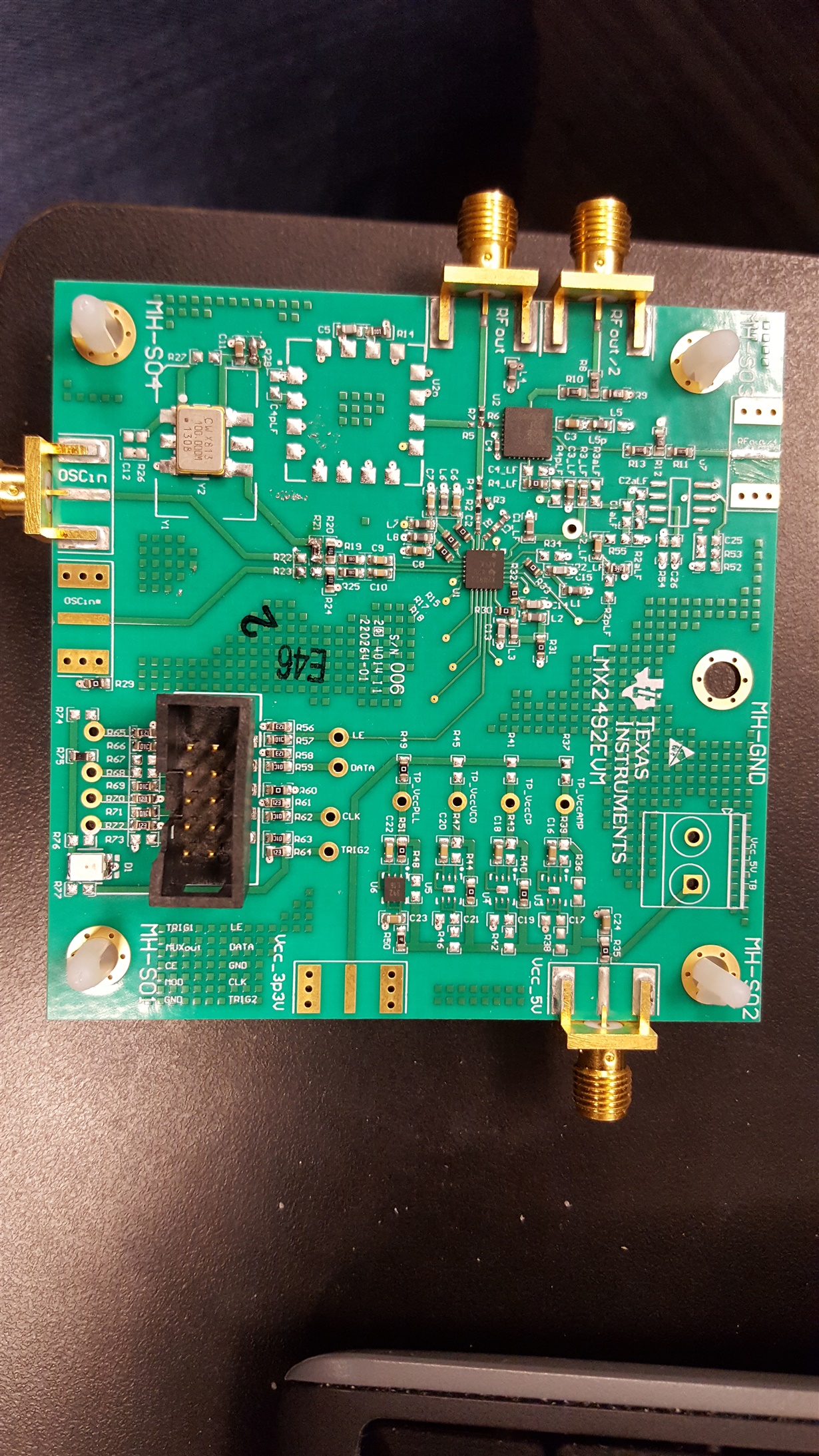
    Here is a picture of the LMX2492EVM that I use, which I ordered from ti.com.

    As you can see there are some components that are in the schematic but are not placed in the board because they are optional, or are for user configuration as Dean explained earlier. 

    The only modification I did to this board was to place the two resistors(R28 &R21) to connect and power the on-board XO and I was able to get an output.

    From your codeloader tab it seems that your PC recognizes the USB2ANY. You mentioned when you pressed CTRL+L you noticed the current changed. 

    That means that you are communicating with the device. As Dean mentioned, when you go into the bits/pins tab, and change it from "powered up" to "powered down" do you see a change in the current supplied from the power supply?

    Also I believe for 4.8GHz and 9.6GHz a spectrum analyzer would be better. Do you have access to one?

    Thanks,

    Julian

  • Hi Julian,

    Thanks a lot...still no luck. I do have a spectrum analyzer HyperLOG 7040 from Aaronia, but it covers 700MHz to 4GHz only.

    What's the way to enable RF/4 to see something.

    Also, I am puzzled where are filter components on the board...it seems Op-Amp of the filter and some 0ohm bridging resistors   R3aLF, R55 are missing. If that is true, expecting output on VCO terminals is madness. But I tried to tap onto CPOUT as well on TP_vtune, it shows some DC signal on oscilloscope, but don't show any change when changing PLL settings....frequency change, ramping etc.


    Best Regards,

    Babu

  • Hi Julian,

    I ordered one replacement board of same PLL from mouser believing that current board might be faulty....but have not opened it yet as suggested by mouser. If you believe current board is faulty, I can open the new one and do the same testing on that.

    Best Regards,

    Babu
  • Hi Julian,

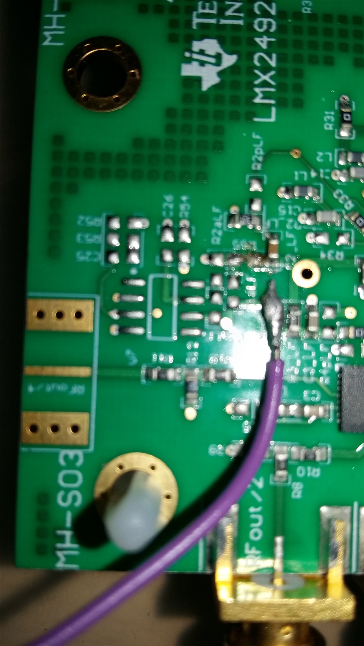
    In order to enable RF/4, I have unsoldered L5p, and soldered at L5 as mentioned in the datasheet. Also, I have made soldered 0ohm connections in place of R55 and R3aLF as active filter part of the board seemed to be disconnected to me from the PLL.

    Despite all this effort, I don't see any output on my Spectrometer, which covers the range of RF/4 adequately (700MHz to 4GHz)....I have exhausted all the options now.

    What do you suggest ???

    Best Regards,

    Babu
  • Babu,

    Have you first tried to get the board working in the default configuration?   By changing the board, this adds more degrees freedom for things to go wrong.   Also you might find this blog I wrote on getting the PLL to lock useful:

    https://e2e.ti.com/blogs_/b/analogwire/archive/2016/07/12/what-to-do-when-your-pll-does-not-lock

    In the case here, changing the inductor L5 should create an ouptut around 2.4 GHz at the RF/4 output and the span you have should be wide enough to see it, regardless of if the PLL is locked or not.   The VCO on this board consumes on the order of 40 mA and the VCO is about 250 mA, so you would see the current of the VCO if it is running.

    For the active filter, you need to also disconnect R3_LF and also ensure that power is to the op amp supply.  Ensure that R54 and R36 are placed.

    Regards,
    Dean

    Lik

  • Hi Dean,

    Could you precisely tell me following. Where is the Op Amp chip on the board ?...I see empty slot in place of it, please see in the pics I posted in earlier post.

    Where is R36 which you are referring ?

    I had high opinion of TI in terms of products but it has been big disappointment this time. Why all the wiring things one after other I am being told, not part of the datasheet...this is annoying me as I have wasted several weeks just in getting started, which should be a straight forward thing.

    Could you ship me a fully tested board...I can ship back mine one to you.

    Best Regards,

    Babu