This thread has been locked.

If you have a related question, please click the "Ask a related question" button in the top right corner. The newly created question will be automatically linked to this question.

TRF372017: TRF372017 OIP3 at L band

Part Number: TRF372017
Other Parts Discussed in Thread: TRF3722, TRF3722EVM

Hi,

I am using TRF372017 as a I/Q modulator to operate at 1.65GHz, According to datasheet, the OIP3 can be 25dBm at L band, and P1dB is about 11dBm. 

But when I tested the OIP3 with two tone (150KHz space) on EVM board, and I can not get 25dBm OIP3, only around 20dBm at 0dBm output on our EVM board .

I do not know if the RF output of TRF372017 was matched to 50 ohm cross a wide band. and there is no impedance information on datasheet. on the EVM board, there is only a 22pF capacitor at the RF output.

As to OIP3, normally the output matching will affect OIP3 very much, Could you please tell the optimized matching impedance for OIP3 at 1.65GHz?

And are there any configuration setting in the chip to optimise OIP3?

Thank you very much!

Jerry Chen


  • Hi Jerry,

    I am looking into this.

    Abdallah Obidat

  • Jerry,

    The best load matching you could do for this modulator is simply 50 ohms, which was determined empirically.  Judging by figure 52 of the datasheet, however, it seems that your result is somewhat reasonable. You could consider operating at a different common-mode voltage, or baseband voltage level. See Figures 55 and 56 of the datasheet.

    Regards,

    Abdallah 

  • Abdallah,

    Thank you for the quick response.

    Do you mean all the OIP3 data in datasheet were measured with 50ohm load cross the band from 700MHz to 2700MHz?

    On our EVM board(TI's EVM) without any matching, we can get about 25dBm OIP3 at 850MHz, and only 20dBm OIP3 at 1650MHz. Vocm was biased at 1.7V. and tried other voltages,1.7V~1.8V is the best range, and no big difference in the range.

    At 1650MHz,I tried a serial 3.0nH inductor at the modulator ouput as matching circuit, the OIP3 can be improved to about 24dBm at 0dBm output power(2-tone,space 150KHz,-3dBm each tone), but the bandwidth with 24dBm OIP3 is only about 40MHz.

    For the Figure 56 in the datasheet, normally, the input single ended baseband voltage 300mVrms(or-10.45dBV),

    differential voltage is -10.45dBV+6=-4.45dBV
    -4dB convertion gain,
    then output is -4.45-4=-8.45dBV
    or-8.45+13=4.55dBm(each tone)
    Total ouput power :4.55+3=7.55dBm
    And the P1dB is 11dBm
    So the test tones are very high.

    0.5Vrms single ended input basebande will drive the modulator close to saturation, so almost half of the data in the figure 56 in the datasheet are meanless.

    Could you please check your EVM board at L band? I still think the OIP3 should has an optimized impedance at different frequency.

    Thank you very much!

    Jerry
  • I'm going to attempt to reproduce your setup in the lab. What are the frequencies of your baseband tones?

  • Abdallah,

    We feed a 75KHz sin wave tone on both I and Q channel, the TRF372017 output frequence is 1.65GHz+/-75KHz, the two tone space is 150KHz. and the output power is around 0dBm.

    Please also check the OIP3 at high and low frequency of 1.62GHz and 1.68GHz.

    Thank you very much.

    Jerry

  • Hi Jerry,

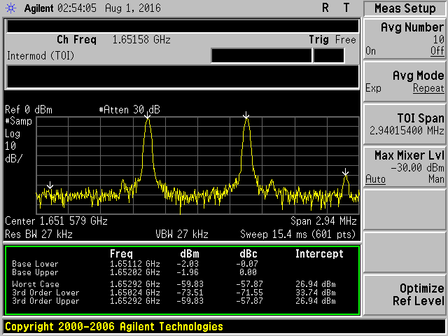
    I measured OIP3 using 75kHz on I and Q, and found a result that is comparable to the datasheet. My only other suggestion would be to offset your input tones from DC, such that the IM2 product doesn’t fall directly on the second harmonic of your signal (which will be modulated as well).

  • Hi Abdallah,

    Thank you for the testing and suggestion!

    Regarding to the test plot,could you please let me know:

    1. What are the baseband signal on I and Q? Are they both sin wave of like cos(2*pi*75KHz*t)? or can you describe the I/Q in mathematical expression?

    Is there any frequency offset of base band signal in your test?

    2.For Lower 3rd IMD, It looks like the actual 3rd IMD frequency should be 1.64978GHz, not 1.64977GHz if the space of 2-tone is 150KHz, right?

    then what are the 2 spurs(noise like) very close (around 10KHz away) to the 3rd IMD?  Are they from LO's phase noise? or do they have any relation to baseband signal of 75KHz?

    Thanks again,

    Jerry


  • 1. Yes they are both cosine waves at 75kHz.

    2. There is no frequency offset in the test results shown above. The baseband signal is centered at DC.

    3. I believe that the 3rd IM is at the correct frequency, and the spacing is indeed 150 kHz.

    1.65 GHz – 75 kHz = 1.649925 GHz, and that minus 150 kHz gives you 1.649775 GHz. I’m assuming that my signal generator can display only so many significant digits, and it may have truncated the value, rather than round it. I think that this is the cause of the discrepancy. 

    4. The spurs seem to be caused by the device itself. I do not think it is related to the baseband signal, as I measured OIP3 on TRF3722 and they were absent. If they are the main issue, you could consider using the TRF3722 as it had similar OIP3 performance at this frequency.

    Regards,

    Abdallah

  • Abdallah,

    Thank you very much for the answers!
    1.Could you please send me a copy of the REGISTERs'setting, Maybe I missed some settings.
    2.Thank you for the suggestion of TRF3722, I notice that the Vcm is only 0.25V,which is very small, maybe it is good for wide bandwidth modulation with SSB. But our application is narrow bandwidth upto 150KHz and DC was include. Are there any good suggestions for design an active LPF on the baseband with Vcm=0.25V?

    Regards,
    Jerry
  • Regrettably the file has been changed since I made the above measurement. However, if you follow the attached users guide, and start from the default settings, you should only have to change the RF Step Size, LO Frequency, and maybe Vref, which is used to adjust the Vcm. Hit the calc button on the GUI to have the program automatically change any other registers related to producing the desired LO frequency.

    For the TRF3722, I would suggest starting with the LPF filter that is on the TRF3722EVM schematic, which I’ve attached.

    slwu068a.pdf

    TRF3722RGZEVM-SCH_A.pdf

    Hopefully this helps.

    Regards,

    Abdallah

  • Hi Abdallah,

    Thank you very much for your kind help!

    One more question, Which one do you prefer to for the application at 1650MHz? TRF372017 or TRF3722?

    Best Regards,

    Jerry

  • Hi Abdallah,

    Could you please tell how OIP3 changes Vs the baseband signal level of TRF3722? there is no such data on the datasheet. we are going to to have the modulator RF output operates in the range of -10~0 dBm around 1650MHz.

    Thanks,
    Jerry
  • I will test this in the lab. I'm assuming that your baseband signal of interest is still +/-75KHz, spaced 150kHz apart, is this correct?

  • Abdallah,

    Yes, please use +/-75KHz of the two-tone.

    Also I notice that the return loss of RF output at 1800MHz is 6dB, Assume all the OIP3 data was gotten at 6dB return loss, which is very poor matching.

    Then how will OIP3 change if the RF output is matched to 50ohm? 

    Thanks,

    Jerry

  • I’ve attached a plot of the worst case OIP3 for the TRF3722EVM. As the output power increases, the IM tones are higher in magnitude. In any case, the 1dB compression point is typically at 10.2 dBm for this device, so I would recommend staying below that to ensure linear operation. Nonlinear effects can observed at an output power of 5.5 dBm.

    Also, this part, unlike the TRF3720, should show improved results by matching the output to 50 ohms. I suggest that you take a look at the TRF3722EVM schematic, to get a good starting point.

    I was able to achieve 30 dBm, using the test conditions specified on the datasheet (Two tones, 1MHz separation, centered at 5MHz). As I mentioned earlier, I still believe that having your IM2, so close to your baseband signal and having it land on top of your second harmonic is bringing down your OIP3. I believe that if you were to increase your signal spacing and have them offset from DC you will see improved results. I’ve attached a screenshot of two tones at 1.125 MHz and 2.025 MHz, and a significant improvement can be observed. 

  • Abdallah,

    Thank you for the detail test data!

    Assume you test on the EVM board without any matching at 1650MHz, then the OIP3 is lower, we can see the OIP3 is about 23dBm at 0dBm output in the plots of OIP3 Vs Output power.

    Do you mean the OIP3 will be improved to around 30dBm when the RF output is matched to 50ohm?

    In the screen shot below,1. what are the spurs close to the main carrier? 2. why the upper side 3rd IMD is much higher than the lower side IMD?

    Regards,

    Jerry

  • Jerry,

    It is expected to observe some asymmetry when measuring OIP3; in this case, this is partially suspected to be a limitation of the instrumentation used.

    The spurs you see are the result of the third harmonic being modulated from baseband.

    I don’t think that the main issue is caused by matching. The above capture was meant to illustrate that your issue stems from your baseband signal and that increased signal spacing, with an offset from DC would improve OIP3 significantly. The signal that you’d like to use isn’t offset from DC, which means your HD2 is falling on your IM2. Also, due to the relatively low frequency, IM4, IM5, etc… may no longer be insignificant and are also being modulated with your baseband signal.

    You will probably see an improvement if you employ matching. But I think the solution would be to further space the signals apart and have them offset from DC.

    Regards,

    Abdallah