This thread has been locked.

If you have a related question, please click the "Ask a related question" button in the top right corner. The newly created question will be automatically linked to this question.

TRF3722: operational support on board testing.

Part Number: TRF3722

our customer working on  IQ modulator IC TRF3722, facing problems Regarding carrier suppression and amplitude imbalance.

.

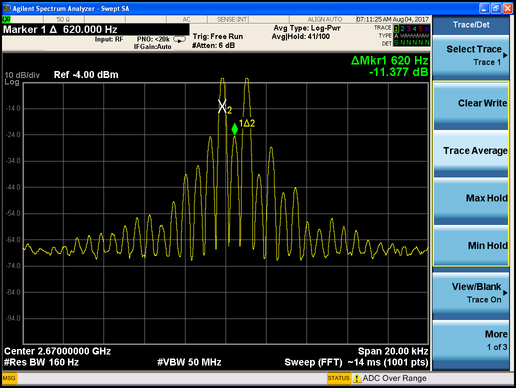
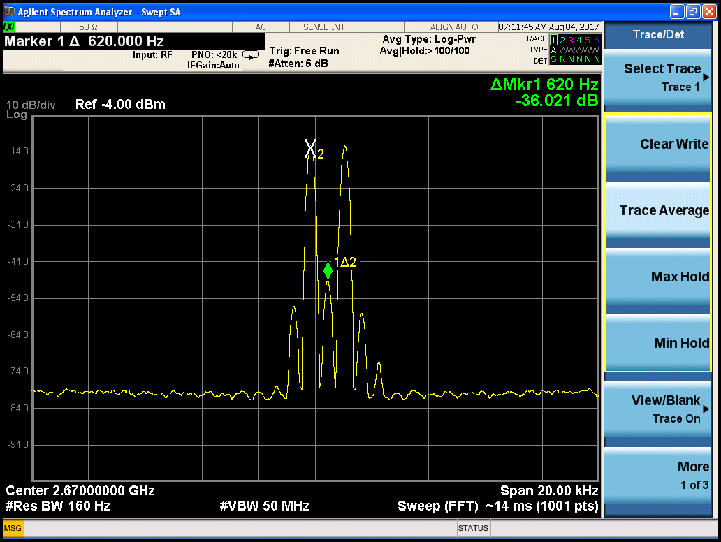
pls find attached plots when operating TRF3722 IC with I,Q signals of 600Hz and LO freq of 2670MHz.

When operating with normal mixer the spectrum plots are good compared to TRF3722 IC.

Please help us in understanding degraded performance of TRF3722 IC compared to normal mixer.Normal_Mixer.zipTRF3722.zip

  • I will look into this.

    Regards,
    Oscar
  • Hello,

    After trying to replicate issue on my own set-up it seems like the issues that the customer is experience are common-mode offset and gain imbalances. I would suggest having the customer play around with the I & Q settings until they find the optimal configuration. I have included screenshots of my attempt to replicate the problem to showcase just how significant having the proper common-mode offset and gain balance can be on the TRF3722.

    No adjustments:

    ,

    With Adjustments

    Regards,

    -Oscar

  • Hello oscar,

    Now I am varying the common mode voltages of I+,I-,Q+,Q- using four potentiometers. The output is still not satisfactory.

    Can we know the test setup you used for generating above captures?

  • Hello Nirmala,

    Is that common-mode voltage the only setting that you are changing? To improve perfomance of the output you may also need to modify the balance of the I/Q amplitude and as well as the phase.

    For my test setup, I used an ESG vector signal generator to inject two tones, of 1.2KHz of spacing, into the modulator with a LO at 2.67GHz. I did not know the exact setup, so I tried to replicate as best as i could. Can you share the details of your set-up so that I may better understand the entire situation?

    Lastly, when you varied the common-mode voltages, did you see any change at the output?

    Regards,
    -Oscar
  • Dear Oscar,

    We are giving I,Q signals to TRF3722 through FPGA, DAC, 2 cascaded LPFs and opamp level shifters.

    We changed the common mode voltages only but we are able to observe very slight difference in output which is not as per expectation.

    The FPGA generates two 600Hz cosine signals into I,Q branches of DAC.

    Please comment.

  • Hello Nrimala,

    While adjusting the common mode voltage may give better carrier suppression performance, this will have little effect on sideband suppression. Have you tired changing any other settings like the I/Q amplitudes and phases? This will have the biggest impact on sideband suppression.

    Regards,

    -Oscar

  • Hello Oscar,

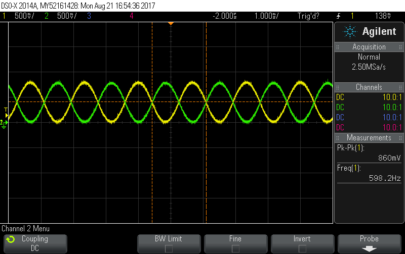
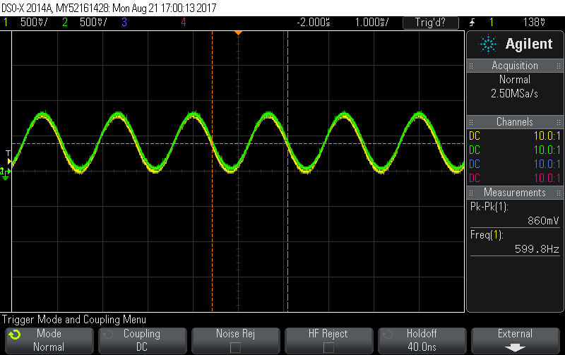
    I am attaching the I+,I- and I+,Q+ signal plots going to TRF3722.

    There is no amplitude or phase error as we can observe.

    Please comment.

  • BS:

    Your original screen plots look strange to me. In a typical modulator output you will see the wanted sideband (2.67GHz + 600 Hz in your case), the carrier feed-through component (2670 GHz in your case), and the suppressed lower sideband (2.67GHz - 600 Hz in your case). Your screenshot shows low amplitude and no sideband suppression.

    If the 1st O-scope plot is I+ and I- then no issue there. If the 2nd O-scope plot is I and Q then these signals should be in quadrature. If they are not in quadrature, then you will not get the sideband suppression.

    It looks like there is also some other PLL issues. Verify that the device is set-up in fractional mode with a relatively high PFD setting (20-35MHz). The signal swing looks OK but try backing off a few dB to see if there are any improvements. The high harmonic content and low fundamental amplitude look like the device is overdriven.

    --RJH