This thread has been locked.

If you have a related question, please click the "Ask a related question" button in the top right corner. The newly created question will be automatically linked to this question.

FDC2114EVM: Slow Communication

Part Number: FDC2114EVM
Other Parts Discussed in Thread: FDC2114

Hi Team,

for my project I need to get at least 6000 SPS out of the FDC. I tried to use an Arduino Mini Pro 3,3V as well as an Raspberry Pi B+, but I never get close to this point, even if the theoretical maximum is 13,3kSPS.

I use 4,7kOhm Pullups and clock frequency is set to 400kHz.

On the Arduino, I measured the time which passed while filling an Array of 100 Samples: 244.000µs/100Samples --> 244µs/Sample --> 4098 SPS

On the Raspberry, I measured the time which passed while filling an list of 10.000 Samples: 8361704µs/10.000Samples --> 836µs/Sample --> 1196 SPS

Why is the Communication that slow, espeacially on the Raspberry which should have enough power to receive this amount of data? What am I missing?

  • Hello Jonas,
    It is likely overhead from the microprocessor that slows down the overall throughput. I would recommend probing the I2C lines from the FDC2114 and/or set the INTB pin to flag new data ready and check that as well. You should notice that the data coming out of the FDC should match very closely to the expected conversion time based on the reference clock frequency and RCOUNT values.
    You will likely need to optimize the code in your processor to give the fastest speeds. Note that typically there is some overhead if you're using an RTOS. For the Arduino or Raspberry PI I would recommend visiting their support forums and asking your question there. If you end up using one of TI's microcontrollers you can ask your question to our experts over on their forums: e2e.ti.com/.../
    Regards,
    Luke
  • Hi Jonas,

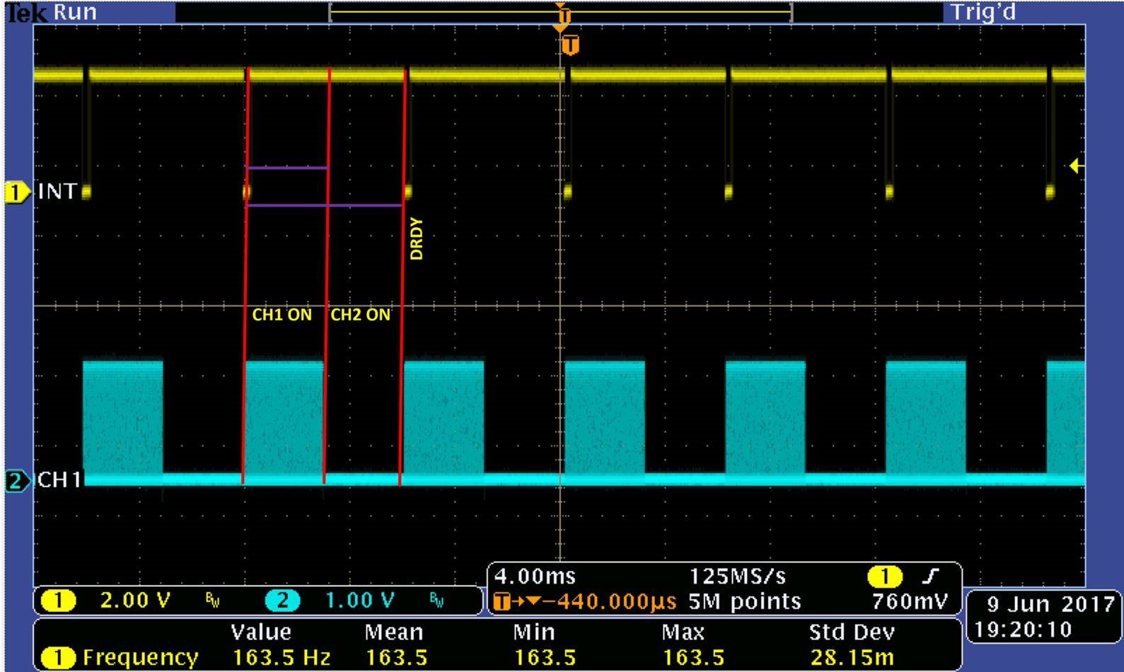
    Have you tried configuring the INTB pin to trigger on DRDY and then probing the INTB pin with a scope to check the conversion time for the device?

    With this INTB functionality with Error Config (Reg Addr 0x19) Bit 0 set to 1:

    A DRDY flag is raised after the round robin conversion cycle (all enabled channels have been sampled) finished. The INTB is normally high and is brought to a logic low level when the DRDY flag is raised.

    The setup below shows the INTB functionality when two channels have been enabled. INTB high duration is twice the length of CH1 sampling duration, after which INTB goes low until the STATUS register is read and a new conversion begins.

  • Hello,

    thanks for your answers.
    But until now I did not look on the INTB, but it seems not relevant, because if the FDC2114 samples slower then I read from the chip, I read the same value multiple times.
    But I recognized the following behavior: When using the Raspberry, the speed of connection depends highly on the I2C speed. Therefore I played with different clock frequencies. As you could imagine, the chip gets faster when using higher clock frequencies. The fastest I reached was around 6000 SPS with a clock frequency of 800kHz (!) which worked pretty reliable for 27 hours before getting the first error message.
    For simplicity I use python for now and this is my code for reading the and measuring the speed:

    def readData(reg):
    start_time = time.time()
    data = []
    for i in range(10000):
    read = FDC.read_i2c_block_data(address, reg, 2)
    data.append(read[0] & 15)
    data[i] = data[i] << 8
    data[i] += read[1]
    timedelta = time.time() - start_time

    Furthermore the status of the python process says "D" which means that it is waiting for I/O.
    For me it seems like a problem in I2C timing.
    Or am I doing something wrong which results in this behavior?
  • Hi Jonas,

    You can use the Inductive Sensing Design Calculator Tool, in the LDC131x/LDC161x Config you can enter the RCOUNT and divider setting to figure out the max sample rate possible.

    Regards,

    Varn.