This thread has been locked.

If you have a related question, please click the "Ask a related question" button in the top right corner. The newly created question will be automatically linked to this question.

FDC2114: Measuring Water and Salt Water

Part Number: FDC2114
Other Parts Discussed in Thread: FDC2214, FDC1004, TIDA-00317

Hello,

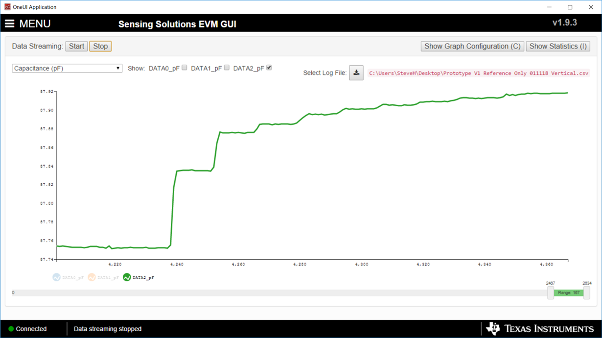
I'm looking to develop a capacitive liquid level sensor for measuring water with various amounts of salt and possible other ingredients. I chose the FDC2214 over the FDC1004 due to the LC-resonator architecture, and it's ability to sample in the MHz range, which should allow measurements of conductive liquids. I've done early testing with distilled water, trying to develop a reference sensor at the bottom of the container to monitor the permittivity of the liquid, since it may change in composition over time. The results of the testing are showed below:

The sensor consists of two parallel plates, about 20 mm x 10 mm each, on a two-sided pcb, with the back side grounded. The sensor is facing the container, and the area in front of the sensor is filled with water after the second step (increase in capacitance). Each step increase in capacitance represents depositing a consistent volume of liquid into the container. So beyond this point, changes in the capacitance of the sensor should be correlated to changes in the permittivity, to adjust the level equation as seen in TIDU736A.

However, as you can see, the capacitance continues to increase as the total volume of liquid in the container increases. I'm confused as to why this is happening, since the FDC2214 is supposed to be better-equipped to handle conductive liquids. Also, in TIDU736A, the FDC1004 is used to test water, which is the same liquid I used for our testing (distilled water). Yet, the Reference Liquid (RL) sensor value does not change according to the results in the TI application note despite higher levels of water.

Please let me know if anyone can offer any assistance in trying to figure out what the problem is, this is the third capacitance sensor we have attempted to use. Also, we're using the FDC2214 evaluation board, and the sensor frequency for the channel used was 4.005 - 4.001 MHz

  • Hello,

    Thanks for posting your question as well as the raw data. Let me see if I understand the problem correctly. You are using a reference liquid (RL) sensor that is completely submerged inside the liquid, similar to the RL sensor of TIDU736A, but even after it is fully submerged its capacitance continues to increase when you add more water to the tank. Is this correct?

    If this is the case, then I would double check the following items:

    • The RL sensor and fringing field is not completely submerged:
      • The capacitive sensors have a fringing field, so just because all of the sensor metal is below the surface of the liquid it can still continue to change capacitance as it gets more full due to the fringing field lines not being fully submerged. That's why the region near the bottom of the container has a slightly non-linear response compared to when the tank is more full. You can see this effect slightly in figure 3 of the TIDU736 document on page 7. It is just harder to see because the scale is zoomed out compared to your plot. You can account for this with your post-processing or you can use a slightly smaller height sensor for the RL sensor.
    • The uniformity of the liquid inside the tank:

      • If you are using additional ingredients such as salt or other that potentially sink to the bottom of the container, then adding more liquid would mean that you are changing the dielectric of the liquid near the RL sensor. You could double check this by ensuring that that solution is stirred or shaken to mix well before pouring into the tank.

    • The temperature of the liquid:
      • It could be that the temperature of the liquid inside the bottle is different than the temperature inside the tank and you are seeing the temperature slowly change the dielectric, especially for the tail end of your waveform. You can double check this by filling the tank completely in one pour then watching the raw code for a longer period of time.

    Also as a performance improvement, I see that your capacitance change of the RL sensor is only about 100fF on the inital pour. This may likely be due to the ground pour on the backside of the container. If you can do a board iteration then you consider to increase the board thickness to increase the separation between the sensor and the ground plane. And additionally consider using a hatched ground pattern instead of a solid ground pour. This will reduce the amount of capacitance generated between the sensor and ground which will increase your sensitivity. Lastly I would double check your LC tank values themselves. Using a smaller capacitor will help increase the sensitivity of your signal.

    Let me know if any of these suggestions help.

    Thanks!

    Luke LaPointe

  • Hi Luke,

    I appreciate your well-thought out and comprehensive feedback. Over the past few days I've run a variety of tests, with mixed results. We removed the ground plane on the back of the sensor PCB's, which allowed us to achieve four times the signal, so we're glad to know that should be able to at least double the signal with a well-designed ground shield. Thank you for your note on that, we're also going to look into using a smaller capacitor.

    Unfortunately, we have still seen the same error in the reference sensor readings. The capacitance value continually increases by up to 20% (of the range) between the saturation point and the final volume. The final volume is typically three times the saturation volume, which is also 3 times the height of the sensor. We've used distilled water in all of our tests to match those conducted in TIDU736A. We're confident the liquid is not changing, and the temperature is remaining consistent as well, since we conduct multiple tests in succession over a short period of time. But those were good suggestions.

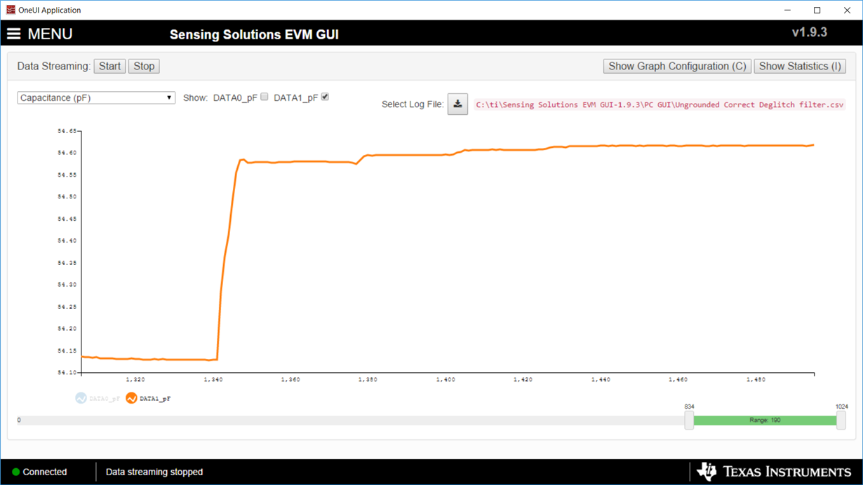
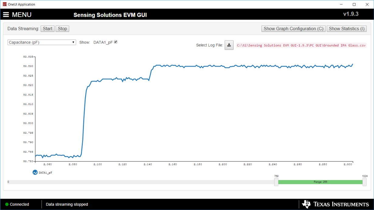
    We ran a test today using a graduated glass cylinder instead of the polypropylene container we're using in our system, and we observed the same results. I've attached a graph of our test using distilled water in a glass graduated cylinder below, where the first step represents the sensor being saturated (+ about 10% to help compensate for fringe effects), and the final step represents water at 4 times the sensor height.

    Since the 20% error remains consistent, even when the signal is increased, it appears that it's being caused by something fundamental. My first thought is that the testing in TIDU736A may have compensated for this phenomenon using the Out-of-Phase method. As we've continued to discuss this, we believe the changes may be resulting from parallel capacitance between the plates and the water, which is compensated for by the OoP shielding technique. We conducted a test yesterday in which we grounded the water, under otherwise the exact same conditions as the previous graph. I've uploaded the graph for the data:

    You can see that the increase is lessened by grounding the semi-conductive liquid. The error was 4.5%, as compared to the 10% increase we had seen when the distilled water wasn't grounded. We believe that grounding the liquid may have decreased it's ability to build up capacitance between each individual plate, which effectively removed the capacitance parallel to the sensor.

    One final thing; we noticed that when we tested oil, there was no increase beyond saturation (I believe the second small-step was from the fringe field above the sensor, as you had mentioned before). See the graph below:

    This supports our theory that the increasing capacitance has to do with the conductivity of the liquid, and particularly the liquid's ability to store capacitance between both plates. We're going to test with the FDC1004 to develop the Out of Phase shielding method in our setup to see if we can better-replicate the results of TIDU736A, and hopefully cancel out the parallel capacitance effects. We appreciate your help and pointing us in some of the right directions, I'll send another note if we get the OoP technique to fix this issue; it may be something other customers run into in the future. Also feel free to comment on any of the results.

    Thanks again,

    Steve

  • Hi Steve,

    Thanks for the feedback and we look forward to hearing the new results. I thought of one additional thing to consider which is:

    • Routing of RL:
      • If the routing of the RL sensor goes to the top of the tank then the traces themselves will act like a sensor and sense the liquid height even beyond the height of the RL sensor. This is the reason that on the TIDA-00317 we have the routing on a flex PCB where the traces are all routed to the bottom of the container so that they do not "see" the liquid on their way back to the device. If you do have a scenario where the electronics are at the top of the container or you have to route the sensor trace over the liquid then we would recommend to bury the traces between ground layers so that the ground shields the traces from the liquid and keeps the capacitance more constant.

    It is interesting that your profile changes if you ground the liquid or not. The advantage of the FDC1004 as you pointed out is the ability to route the sensors out-of-phase which keeps the liquid at a constant potential. If this is the culprit then the FDC1004 solution should solve the issue.

    Let us know how it goes.

    Thanks!

    Luke