This thread has been locked.

If you have a related question, please click the "Ask a related question" button in the top right corner. The newly created question will be automatically linked to this question.

AFE4300EVM-PDK: Phase is opposite sign of expected result

Part Number: AFE4300EVM-PDK
Other Parts Discussed in Thread: AFE4300

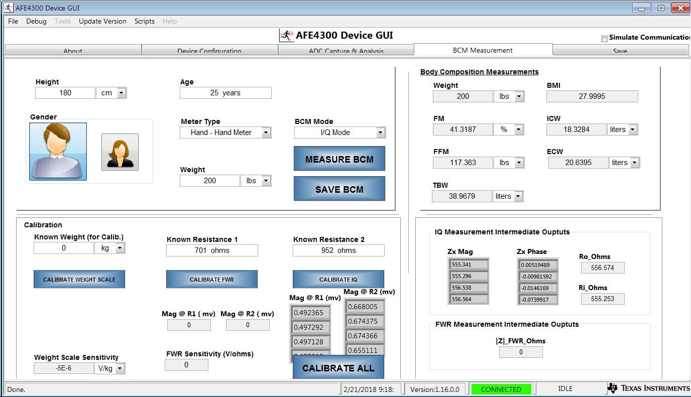
I am using the AFE4300-EVM Rev B and am referencing the TI document "Impedance Measurement with AFE4300" (SBAA202 - January 2013).  I am trying to reproduce the results shown in section 3.2.2 Table 3.  I am getting similar Mag_M values (shown as Zx Mag in GUI) but the Phase_M values I am seeing (shown as Zx Phase in GUI) are roughly the same degree value except for the sign (i.e. I am reading 19.2 instead of the optimal -18.06).  This is true for all 4 frequencies.

I am using a 100 nF capacitor and a 550 ohm resistor.  I have not measured the exact values of either components but I thought they should be close enough to see similar results.

Can you think of a reason the phase I am reading is the opposite sign that Matlab calculates and that the Table 3 tests show?

Thanks, Jeff

  • Hi Jeff,

    Are you injecting the excitation current in the same direction as given in the SBAA202?

    Regards,
    Prabin
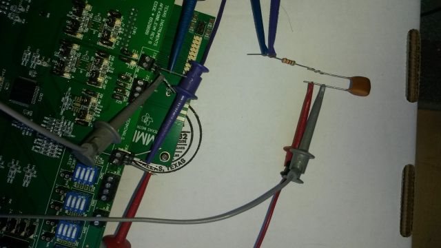
  • Yes and I have tried swapping the direction but get the same result. See image below of my setup. I also attached a screen shot of the GUI screen after I selected "MEASURE BCM".

    Jeff

  • Hi Jeff,

    Can you please use the "ADC Capture & Analysis" tab to manually capture the data for the I and Q pahse?
    With these two values you can calculate the magnitude and phase yourself and see if you still get the positive phase.
    I think GUI is designed for impedance with only resistor.

    Regards,
    Prabin
  • I don't really understand what you mean by "I think the issue is with the GUI designed for impedance with only resistor". I assumed that the formulas and steps outlined in SBAA202 (Jan 2013) section 2.2 worked for all the various circuits that may be read from the body. Also the GUI displays the phase for 4 different frequencies so what would be the purpose of showing phase if it only worked on a resistive circuit (i.e. phase of zero). And it is curious that the phase displayed is indeed correct with Matlab except for the sign of the phase.

    I have not performed the manual steps using the "ADC Capture and Analysis" tab in the GUI as you ask, but I have performed these steps using our custom PCB with the AFE4300 installed. On my custom PCB I have executed in IQ mode (following the flow outlined in SBAA202 Jan 2013 Figure 4) and then manually calculated the phase using the formulas (described in SBAA202 Jan 2013 section 2.2) and I get the same phase values as the GUI is showing.

    So to summarize, the GUI and my custom PCB are both showing the same phase values but the sign shown on both of these is the opposite of what Matlab says it should be.

    Jeff
  • Hi Jeff,

    I agree that GUI shows the magnitude and phase but it doesn't have option to input complex impedance as calibration impedance and use the information to correct the reading.
    That is why I wanted to manually compute the magnitude and phase for both the circuits ( series RC and calibration resistors).
    What phase do you get if you only have R ( instead of RC)?

    Regards,
    Prabin
  • Hi Prabin,

    Is there a quicker method to interact with you?  Waiting 3 days for a response is not exactly working.

    I have manually executed and calculated the phase using the exact steps outlined in SBAA202 section 2.2 and I get the correct phase but the wrong sign for the tests in section 3.2.2  (i.e. I get the same results that the GUI displays).  Note that at the last step of section 2.2, the phase of the calibration resistor R1 is subtracted from the calculated phase to get the final phase result.

    Did TI use the EVM-PDK with the GUI application when they wrote the SBAA202 and then ran the tests in section 3.2.2?  I just don't understand the discrepancies between the GUI (and my manually calculated values) and the expected test results in section 3.2.2.  Could you try it on your end?

    Thanks,

    Jeff 

  • Also to answer you question: I ran IQ mode on just a 550 ohm resistor network and the phase values are pretty much zero degrees (see attached GUI screen shot).

  • OK, as per your request I ran manual tests on the EVM-PDK using the Low Level Configuration tab.


    For the 550 ohm resistive network at 8kHz I got the following values:

     A/D for reading I of the output network: 4633

    A/D for reading Q of the output network: -5942

    A/D for reading I of the internal calibration Rx resistor: 5833

    A/D for reading Q of the internal calibration Rx resistor: -7475


    PhaseRX = arctan(-7475/5833) = -52 deg

    PhaseOUT = arctan(-5942/4633) = -52 deg


    Phase = PhaseOUT – PhaseRX = -52 – (-52) = 0 deg   (this is the expected value)

    For the 550 ohm / 100 nF RC network at 8kHz I got the following values:

     A/D for reading I of the output network: 6865

    A/D for reading Q of the output network: -4228

    A/D for reading I of the internal calibration Rx resistor: 5834

    A/D for reading Q of the internal calibration Rx resistor: -7474


    PhaseRX = arctan(-7474/5834) = -52 deg

    PhaseOUT = arctan(-4228/6865) = -31 deg


    Phase = PhaseOUT – PhaseRX = -31 – (-52) = 21 deg     (expected is -19.88)

    Note: Matlab says phase should ideally be -19.88 so our Phase value calculated above is correct (given the tolerance of actual components used in our RC network) except for the sign is opposite (we show positive while Matlab shows negative angle).


    Jeff

  • Hi Jeff,

    I found a section in the datasheet that tells the about non deterministic phase in IQ mode and ways to mitigate it.
    Please refer to section 8.1.3 "Achieving Deterministic Phase in the IQ Mode " of the datasheet for further details.
    So looks like taking the phase measurement between calibration impedance and the series RC network at two different time instances will not give the required polarity in the phase.
    Following is the sequence I can think of to mitigate this effect.
    1) Configure the AFE ( including the BCM and IQ clocks).
    2) Change the ISW_MUX and VSM_MUX to measure the output for calibration registors.
    3) Change the ISW_MUX and VSM_MUX to measure the output for body impedance ( series RC in our case).
    Using some kind of automation/scripting to achieve this will help.

    Regards,
    Prabin
  • Hi Prabin,

    Yes I am familiar with section 8.1 and both my software on our custom PCB, my manual test I sent you earlier, and the TI GUI are all conforming to this requirement.  The steps performed are the AFE4300 is first setup for IQ mode in the desired frequency.  Then the calibration resistors are read for both I and Q, and then the output for body impedance is read for both I and Q (actually the TI GUI reads the output for body impedance I and Q values before reading the calibration resistor I and Q values but the order doesn't matter).

    Jeff

  • Any update to the status of this issue?

  • Still waiting for a resolution...

    This is an extremely frustrating and very slow experience. Is there a way to get this resolved using another support method? The issue I am seeing can easily be reproduced using just the TI AFE4300 evaluation board and the TI AFE4300 Windows GUI software along with a simple external circuit (which I posted images of in previous posts on this thread). It would be greatly appreciated if some TI AFE4300 expert would try this setup to see if the same results are observed. I am directly following the setup in the TI reference document.

    This thread is in the Capacitive Sensing Forum and probably belongs in the Medical Forum. Unfortunately the Medical Forum is not an option when adding a new post. So if this thread is not being answered because it is in the wrong forum, then please feel free to move it to the Medical Forum.

    Please help!

    Jeff
  • Hi Jeff,

    Please send an email to praveen.aroul@ti.com if you were not able to resolve the issue.