


Other Parts Discussed in Thread: FDC2214, FDC2214EVM
I have some questions about a capacitive sensing application. We have a potential application where we’d like to measure capacitance with the following specs:
- Minimum 1 kHz sampling (higher is better)
- Want to measure capacitance change of approximately 50pF (some applications may have capacitance change up to 200pF), with a fixed offset in the range of 30pF-60pF. For example, if the offset was 40pF we’d want our total measurement range to be at least 40-90pF.
- Ideally resolution for this measurement range and sampling rate would be on the order of femto-farads.
It looks like the FDC2212/FDC2214 devices from TI are close to meeting our needs, but the specs for sampling rate vs resolution aren’t real straightforward from the datasheet as they’re dependent on the configuration and device settings. I have some initial questions below. I’m wondering if you could help with these or put me in touch with someone who can.
- On pg 14 of the datasheet, Table 1 indicates that the maximum reference frequency for single channel mode is 35 MHz, but there are multiple examples in the datasheet (pg 6 “Note 6”, pg 9 “8.8 Typical Characteristics” test conditions, pg 45 “10.2.4 Application Curves” test conditions) that seem to suggest operation in single channel continuous mode with a 40 MHz reference clock.
- The datasheet (pg 16) says that the “settling wait time” should be set to a value that is long enough to allow stable oscillation. If the device is set to single channel continuous sampling, is a settle count > 0 required? Or is the settle count only required before the first reading and when sequencing between multiple channels on the device?
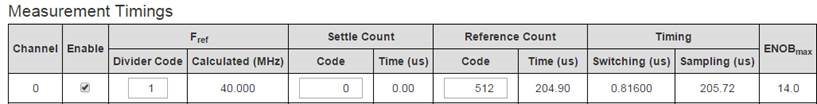
- There is some discussion about Effective Number of Bits (“ENOB”). The datasheet indicates that for 13 effective bits, 2^13 = 8192 clock cycles are required (pg 17). This corresponds to RCOUNT = 0x0200 (0x200 = 512, 16 clk cycles per RCOUNT). But if I enter 512 into the Sensing Solutions EVM GUI for the FDC2214EVM demo board, it indicates ENOBmax = 14. Is this just a bug in the application or am I missing something?
- It’s not clear to me what this effective number of bits represents. If the ENOB is 13, does that mean the resolution of the output is essentially 0Hz to the reference frequency in 2^13=8192 steps? This is my assumption for the calculation below.
- My initial estimates based on my current understanding of the specs is that we’d have a resolution of 10’s to 100’s of femto-farads in our measurement range. This is based on the following assumptions:

-
-
- Fref = 40MHz
- Settle count = 0 (single channel continuous mode)
- Reference count = 2498
- L = 18uH
- Cfixed = 33pF
- Cvariable = 30-200 pF
- Sensed frequency resolution = (2498*16 = 39968) steps over 40MHz = 1.0008 kHz resolution
- Capacitance is proportional to 1/f^2, so does not have a fixed resolution.
-
-
-
-
-
- With Ctotal ranging from 233 pF down to 66 pF, we’d have Fsense ranging from 2.458MHz up to 4.725MHz
- At 2.458MHz, a 1.0008kHz frequency step corresponds to a capacitance change of approximately 190 fF
- At 4.725MHz, a 1.0008kHz frequency step corresponds to a capacitance change of approximately 27 fF
- This resolution is about 10 times higher than we’d like for the application.
-
-
-

If you have any other products that you think would meet our target requirements I’d be interested in learning more.
Thanks
Viktorija
