This thread has been locked.

If you have a related question, please click the "Ask a related question" button in the top right corner. The newly created question will be automatically linked to this question.

DRV421: The relationship between the size of Rshunt and the drift of zero point

Part Number: DRV421

Application is about the residual current sensor(maximum resolution is 1mA(DC&AC), Range 0-100mA)

Therefore, the Rshunt resistance needs to be taken to the K level to ensure the accuracy, but when the Rshunt is taken to the K level, the zero point (2.5V) of the whole system will drift a lot, and the larger Rshunt, the greater drift.

The test found that the R5 Dummy shunt resistance given in the specification can not compensate for the whole zero drift.

Only the Rshunt is less than 100 Ω, the drift is small, but the precision of the measurement is difficult to guarantee. The initial judgment is that the internal H bridge circuit has caused the impact on the Rshunt resistance and differential operation, and the differential input impedance of the internal differential op amp is 20K.

Please help  me   how to ensure the accuracy range and zero drift at the same time.

  • Hello user4308845,

    Thanks for considering to use Texas instruments in your design. We will get back to you on this issue the following business day.
  • Hello user4308845,

    Please help me understand the drift. Does the output change with time or temperature.  Or is the error and initial error?  Is the magnetic core magnetized?

    There are a few key design considerations when measuring low currents.  The first is the material used for the core.  The higher the permeability the better the rejection of external magnetic fields.  Also the lower value in measurement you most likely have a lower number of turns on the compensation coil.  Please make sure you have a stable loop,  we have an application note covering this. Designing with the DRV421: Control Loop Stability.  

    The higher permeability material for the core may also not be enough to eliminate any unwanted magnetic fields.  You may need to create another shied to eliminate those unwanted fields.

    Are you testing the results also with two current carrying conductors?  If so you have have issues where one of the conductors is coupling directly to the DRV421.  This would result in an error as well.  Higher permeability core material and smaller air gap will improve this.

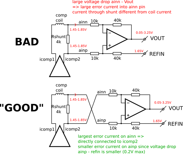
    I have also include a diagram to improve your difference amplifier connection.

  • 1.The DEMAG pin in my circuit is default  high-level

    2.my magnetic core parameter is 

    • internal diameter=12.7mm,
      • external diameter=24.6mm, Gap=0.3mm, material μr=100000, Compensation coil N=500 or 200
      • 3.  when Rshunt=1k ,VOUT=2.3V,there is no primary current,and the bigger Rshunt(>1K), the larger driftaway from 2.5V. when Rshunt=100Ω,Vout=2.495, and the smaller Rshunt(<100Ω) , the smaller drift
        • 4.I've already used the circuit in your map,but there is no change.


  • The test found that the R5 Dummy shunt resistance given in the specification can not compensate for the drift(without any primary current).
  • Hello user4308845,

    I believe your issue is with the demag function.  Because you have a high resistor you are not able to demagnetize the core.  This is because you do not have enough current range to saturate and unsaturated the magnetic core.  One solution is placing diodes in both directions across your shunt resistor.  The diode will conduct current when the part is in the demag function but during normal operation it will not.

  • place two diodes (1n4148)in both directions across the shunt resistor ,but there is no change.

    when I remove the compensation coil , There is still a drift in the output .
  • Hello,

    Please do not remove the compensation coil as it is required for the feedback loop to work. But with that being said if there is no compensation coil the output should be close to the Vref voltage. If this is the case can you verify the inputs into the difference amplifier are the same voltage. One of those pins floating could be an issue.

    Another thing to try is removing the Demag function by forcing the pin low. Check if this is causing the error. I had tried the demag with the diodes before and it was a success.
  • I have tried to remove the Demag function, but the output has not changed much before.

    Do  you  have the successful  case about to the fault  current sensor with the large Rshunt? This issue have effect me  a long time,please  help me

  • Hello,
    Can you please give me your thickness of your core? Also are you shielding it? I will also make some calculations to see what the error you can get just from the offset of the DRV421. The specification is 8uT but I need to simulate your core.
  • thickness is 5.4mm,without any shield.
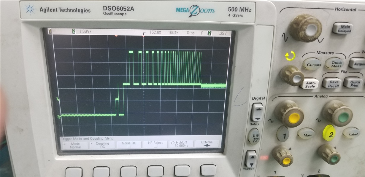
  • this is output waveform in my system

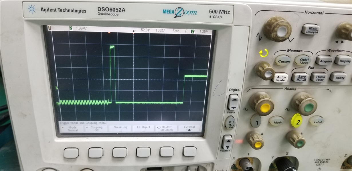
    this is Icomp2 waveform in a DEMAG cycle


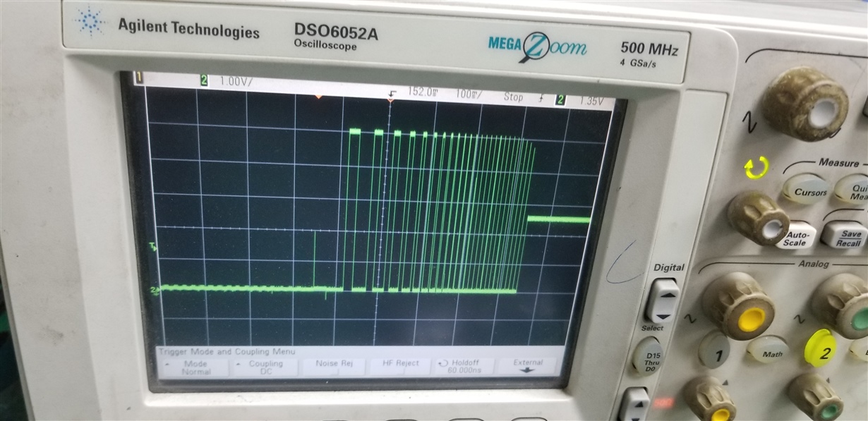
    this is Icomp1 waveform in a DEMAG cycle

    these waveforms are a little different from the SPEC, and I found that in a DEMAG cycle ER pin was still keeping high-level .

    (test condition is Rshunt= 1k)

    when Rshunt <100Ω,it will skip the DEMAG cycle, it makes me puzzled.

    Please check it


  • Hello,

    I am not sure why you are not seeing the Demag cycle during the lower Rshunt values as the Rshunt does not change if the Demag cycle is applied.  You may see the ICOMP pins should hit the rails during the demag function in both conditions.  The output will be based on the Rshunt and the current running through. During the demag the coil must get saturated in order to demagnetize.

    I also simulated the core you described.  I am not sure if this is the cause of the drift as I still think there is an issue with the demag of the core as well which could be related to the number of turns and being able to saturate the core to force a demag.  The core I simulated gave me an inductance of ~40mH.  From the datasheet for the stability we recommend larger than 300mH but 100mH should work.  He have more on this in the document link below.  I have also attached my simulation file which was ran using FEMM a free tool available online.

  • 1. I found that in a DEMAG cycle ER pin was still keeping high-level ,why?
    2. if you still think there is an issue with the demag of the core, the demag current effects the error, I should add two diodes across the Rshunt , about to two diodes, How to choose the type , I choose 1N4148 to fail.
    3. Must the core work in a saturated state in a demag cycle?
  • Hi Javier
    I found my waveform for Icomp2 I measured above is different from SPEC , maybe there is no access to magnetic degaussing at all ,My circuit is designed based on the recommended circuit ,why?
  • Hello User4308845,

    1. I found that in a DEMAG cycle ER pin was still keeping high-level ,why?

    I will follow up on this.  I see the same thing.


    2. if you still think there is an issue with the demag of the core, the demag current effects the error, I should add two diodes across the Rshunt , about to two diodes, How to choose the type , I choose 1N4148 to fail.

    I will try this but this will be dependent on the core and the load seen by the Icomp pins


    3. Must the core work in a saturated state in a demag cycle?

    From my understanding in needs to saturte  In order to demag a core. If the core does not see and offset you can simply turn the demag function off.

    4.I found my waveform for Icomp2 I measured above is different from SPEC , maybe there is no access to magnetic degaussing at all ,My circuit is designed based on the recommended circuit ,why?

    Please be aware that if there is no resistance and Icomp2 is always driving low because id does not see a magnetic field change as it is pulsing you will only see it driving to GND or VDD.

  • Please be aware that if there is no resistance and Icomp2 is always driving low because id does not see a magnetic field change as it is pulsing you will only see it driving to GND or VDD.

    =>> The waveform I measured is that Rshunt and the core are all connected to the circuit.
  • Now
    How should I solve the problem of zero error when there is no primary current now?
  • please help me to solve this problem ,thanks!

  • if  offset is 8uT , N=500 ,primary coil magnetic Gain=4000uT/A(from my design )  ,  So   compensation coil Gain=4000uT/ 2mA .

    when there is no magnetic field,  offset 8uT will generate 4uA error current ,  so when Rshunt =1k,  the differential voltage is 4mv, the output voltage is 2.5V±16mV 

    Is my uderstanding right?

  •  

    if  offset is 8uT , N=500 ,primary coil magnetic Gain=4000uT/A(from my design )  ,  So   compensation coil Gain=4000uT/ 2mA .

    when there is no magnetic field,  offset 8uT will generate 4uA error current ,  so when Rshunt =1k,  the differential voltage is 4mv, the output voltage is 2.5V±16mV

    Is my uderstanding right?

  • User4308845,

    Please excuse my delayed response. The magnetic gain is dependent on the position of the sensor relative to your magnetic core and the air gap size. From my simulations based on the details you provided from the core I simulated the gain between 800 uT/A - 900 uT/A. So if we have an error only coming for the sensor the calculation would be as follows. Please note these are assuming the core is not magnetize. Also I have never attempted a core that has lower inductance than the recommended 300mH.

    8µT / 800µT/A = 10mA error on Primary (Magnetic Gain of 800uT/A)
    10mA/500 = 20µA error current on compensation coil (N= 500)
    20µ*1KΩ = 20mV Voltage input to Diff Amplifier (Rshunt = 1KΩ)
    20mA *4 = 80mV Voltage after Diff amplifier.

    What is the error you get without a engaging the Demag function? You mentioned before you get 2.3V output. Is this core you have available for me to purchase and do some experiments on?
  • the demag function has always existed, I keep the Demag pin high-level at all times.

    ER Pin keeps high-level when the demag function is on, have you solved this problem?


  • In addition, I would like to ask you about your core size, turns and other specifications.
  • My magnetic core can send you two pieces, please give me your address. In addition, I would like to ask you about your core size, turns and other specifications.
  • Hello user4308845,

    I confirmed that ER does not work exactly as the datasheet. I will be working on update to datasheet to remove this statement. It was expected that the ER would trip during the whole operation of the Degauss function but it is not the case only during saturation conditions where the magnetic field saturates the sensor. Since there is a large Rshunt you may never see this in your circuit. I have had other cores that I have used but none have been or low current all have been for either 100A or 10A. They have all had many more turns and met the inductance requirement. I did work with another customer and they were able to get this to work with my suggestion of placing diodes.

    I am having issues degassing all variations of cores in all conditions. I believe this is a core issue and its properties. Can you make a measurement and attempt to get a delta measurement of the current. That is why I suggested taking the degauss function off and make measurements. Also you will need shielding both internal and external. If you do not you will get more errors due to external fields (external shields) and Common Current Rejection issues (internal shield). For internal shield this is where the multiple currents should couple together to create zero field across the core air gap. The issue is that if one of the conductors is closer to the air gap it will couple more to the DRV421 than one further creating an error. The internal shield should be thin this couples the currents together before getting to the other core where only delta's can be measured.
  • The delta of the current I measured is right , The output voltage has a linear change. but the output voltage when there is no primary current is instable and away from 2.5V.

    Could you give me your core spec or size?

  • User4308845,

    I do not have a core on hand that are designed to measure residual currents.