This thread has been locked.

If you have a related question, please click the "Ask a related question" button in the top right corner. The newly created question will be automatically linked to this question.

LMP91000: Definition of load resistance value to use in LMP91000, with a time constant constraint

Part Number: LMP91000

Hello,

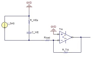
I am currently working on a design including a gas sensor and a potentiostat using the LMP91000 part. I am having some issues in order to define the suitable Rload (10, 50 or 100) for my application. I understand that this resistance is defined as a trade off between S/N ratio and time constant for the measurement. To compute the best value for my case, I thought of modeling the sensor as a current source with internal impedance. By wandering on some litterature and other threads on this forum, I found the following schematic (posted a while back ago by a TI employee) but I am having some trouble understanding why the node between I_GAS and R_WEs is grounded. Maybe I am missing really basic or fundamental here, but I will be thrilled if someone got some ideas or insights on this matter.

Thanks in advance everyone,

Walid
  • Hi Walid,
    the node between I_GAS and R_WEs is the RE electrode of the Gas Sensor. In the LMP9100, the RE pin is connected to the inverting input of the control amplifier (please refer to the functional block diagram at page 13 of the LMP91000 datasheet). When the sensor is connected to the LMP91000, the feedback loop of the control amplifier is closed, and from the signal point of view, the RE node is then connected to a virtual ground.
    Please let me know if this replies to your question.
    Best regards,
    Carmine
  • Hello Carmine,

    First of all thank you for taking the time to answer my question. The behavior you describe is in general what I had in mind, but to my understanding, the RE electrode (and node) is maintained at the Vbias potential thanks to the control amplifier, I agree that this node is a reference but I don't see how (or why) it should be considered as a ground. I would be thrilled if you could underpin your explanation a little more.

    Thanks again Carmine,

    Best regards,

    Walid

  • Hi Walid,
    the RE electrode is maintained at the vbias potential, so you can consider a voltage source connected to it. But when you consider the signal transferring, and applying the Superposition principle, the vbias voltage source has to be switched off, and it has been a 'ground'.
    Please let me know if it is more clear now.
    Best regards,
    Carmine