This thread has been locked.

If you have a related question, please click the "Ask a related question" button in the top right corner. The newly created question will be automatically linked to this question.

LDC1000 not responding

LDC1000 is connected to micro-controller and communicating to it through SPI. 

1) The power mode is set as active.(register - 0x0B,data - 0x01)

2) External Time-Base Clock(TBCLK) is choosen given through controller.(register -0x05, data - 0x00)

On checking on CRO pulses are coming as per the data sent on SDI, CSB and SCLK.But there is no reply coming when a read command is sent to read the device ID.

No other register other the selecting clock and power mode is changed.  

  • Hello Sonam,

    I see you have 0 value in your TBCLK register. You would want to see a value there. Please, check your connections.

    Best Regards,

    Natallia Holubeva

  • Hi Natallia ,

    Thanks for the reply.

    I am supplying a external clock from microcontroller i.e why selected value as 0x00, as per the data sheet.

    After setting clock and power mode as active, when i try reading the device ID of LDC,but no reply is coming.

    Also, Does LDC send some acknowledgement if the registers are written correctly or not.

    Thanks.

  • Hello Sonam,

    Thank you for clarifying. Is your SDO pin connected properly? If you cannot read the ID, there are 2 things that can be wrong: either you are not powering your part, or your SDO is not functionning. No ack are being sent by the LDC.

    Best Regards,

    Natallia Holubeva

  • Hi, 

    I do checked the connectivity of SDO pin to micro-controller through multi-meter it is coming fine. And so does the power.

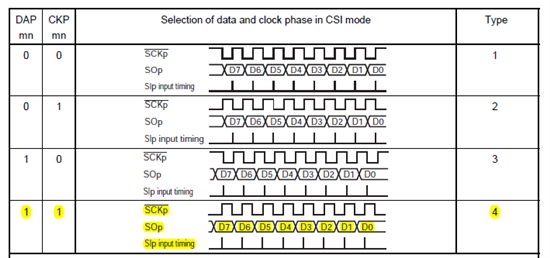
    On SDO pin it is showing a active high on CRO. Do clock phase affect the SDO output? Micro-controller has following options for clock output and have chosen type 4.

    One more doubt is regarding the delay - what is the minimum delay that needs to be provided after every LDC read so that it will have enough time to reply.

    Regards,

    Sonam

  • Hello Sonam,

    The inter-access gap is 100 ns. Please, refer to the timing characteristics described on the page 7 of the datasheet:

    Best Regards,

    Natallia Holubeva

  • Hello Natallia ,

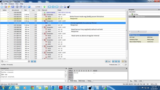
    Thanks for the response. As suggested I am giving more than 100ns of delay. Please find the below screenshot of SPI data analyzer response. It is showing MISO and MOSI data. On MISO line it is always sending FFFF. 

    Configuration for SPI is as below:-

    Type : 4 (please refer type 4 definition in previous reply posted to you)

    Data width : 16 bits (MSB first)

    In write operation I am sending 16 bits. first byte as ( Write bit + register Add) and 0xXX data as 2nd byte.

    In read operation I am sending 16 bits. first byte as ( Read bit + register Add) and 0x00 as 2nd byte. that means total 16 bits in read operation.

    Please confirm it is the right way of LDC read/write operation. or do I need to send only 8 bits during read operation?

    Thanks.,

    Sonam

  • Hi Sonam,

    The MISO pin (SDO) should not always send 0xFFFF. Note that the data read packet from the LDC1000 is only 8bits. I assume you have set the VIO of the LDC1000 to match the MCU's voltage, is that correct?

    Regards,

    ChrisO

  • Hi

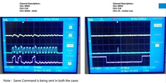
    After trying so many options LDC is not giving any response. Below is the snapshot attached.  In snapshop im trying to read register 0x21 by sending command 0xA1. Before this the TBCLK clock is selected and power mode active is selected as explained in earlier posts. I had also tried to read the device ID by sending 0x80 command but no reply on MISO. 

    Is there any way of verifying if the LDC-1000(hardware chip) is working properly?? 

    Regards,

    Sonam

  • Hello Sonam,

    Firstly, I would make sure that voltages on each pin satisfy the electrical characteristics. Second, please try to read the device ID.

    Best Regards,

    Natallia Holubeva