This thread has been locked.

If you have a related question, please click the "Ask a related question" button in the top right corner. The newly created question will be automatically linked to this question.

How to modify LDC1000 register via MSP-EXP430F5529LP?

Other Parts Discussed in Thread: MSP-EXP430F5529LP, LDC1000EVM

Hi,all:

I only want to modify the LDC1000 register via EXP430F5529LP and CCS v6.0.

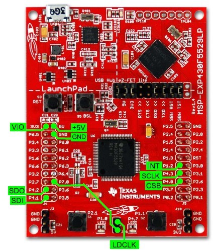
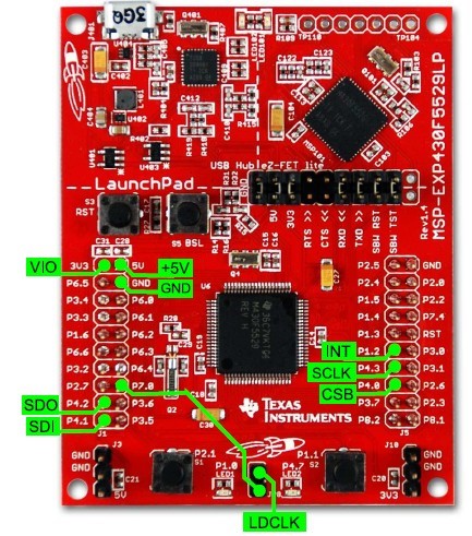
and following below picture to connect  EXP430F5529LP and LDC1000.


(1) I find sample code from Ti's web, http://www.ti.com/litv/zip/snac059.

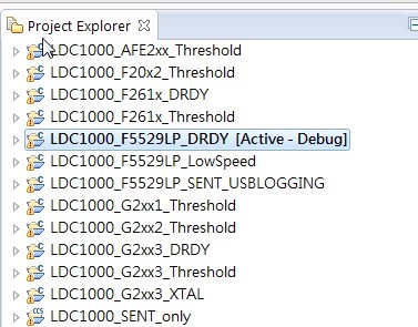
     And import all projects,which project should i build ?

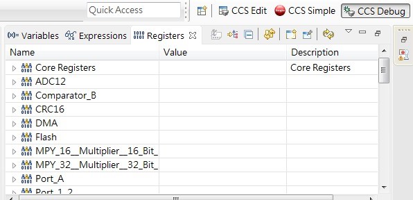
I build and debug LDC1000_F5529LP_DRDY first, and the register column shows the EXP430F5529LP register, not LDC1000 register.

(2) How would I know LDC1000 properly connected to MSP-EXP430F5529LP?

Someone can help me? thanks.

  • Hello Yulin,

    The connections needed from MSP430 to LDC1000 are shown in the figure 2, page 2 of the LDC1000 datasheet.

    Best Regards,

    Natallia Holubeva

  • Hi, Natallia:

    Should i import the LDC1000_F5529LP_DRDY project to modify LDC1000 register?

    Best Regards,

    thanks.

  • Hi Yulin,

    Yes, DRDY register tells you when the data is ready.

    Best Regards,
    Natallia Holubeva
  • Hi, Natallia:

    Ok,i will try to find how to modify register value and read it.
    If i have question, i will let you know.

    Best Regards,

    thanks.
  • PLease let us know if this resolves your issue.REgards,ChrisO
  • Hi Natallia:

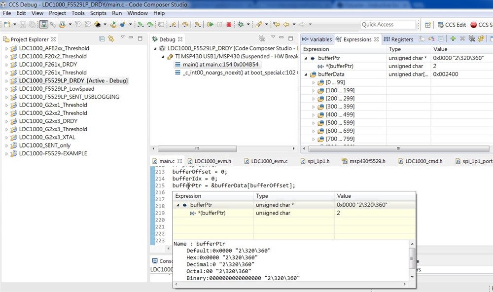
    I want to see the LDC1000 register and used the CCS Expressions to watch bufferPtr value, as shown below:

    I find the  bufferPtr value will not change, it seems that the default value!?
    Also i also check the connection between the launchpad and ldc1000evm  , they are correctly.
    What's problem with me? I follow the Interfacing LDC1000 with the MSP430 LaunchPad.pdf  p.7 connecting.

    Thank you.

    BR. LEO

  • Hello Leo,

    Can you please probe all the pins and LDC1000, clock specifically? Also, please try reading device ID in order to see if you have communication with the device.

    Best Regards,
    Natallia Holubeva
  • Hi Natallia:

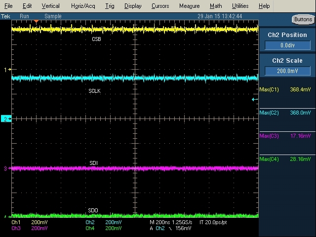
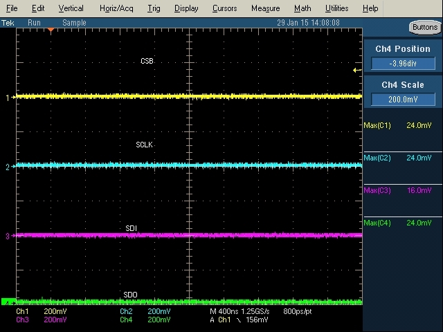
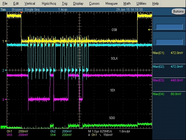
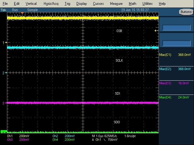
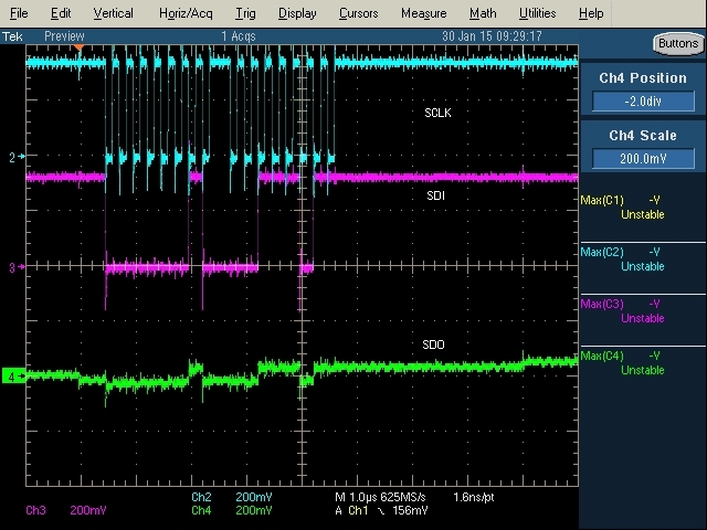
    I measured 4 pins ->CSB,SDI,SDO,SCLK, the probe is 10X.

    pictures as below:

    (1)plug in USB between launchpad and PC:


    (2)After debug:


    (3)Press resume button:


    (4)After press resume button:


    It's confuse me that i don't change (LDC1000_F5529LP_DRDY) sample code any , and following the datasheet connection.

    What's wrong with me? Should i modify some setting?  

    BR.

    LEO

  • Hello Leo,

    I am not sure I clearly understand what you are trying to solve. The communication on figure 3 looks fine, besides the fact you need to show SDO.

    Best Regards,
    Natallia Holubeva
  • Dear  Natallia:

    Upload the no.3 SDO image clearly.

    And i don't know when i resume the code(no.4 image) , the there are no signal appear.(CSB,SCLK is High...SDI,SDO is Low)

  • Hello Leo,

    Based on the scope shot, you are writing the data to the LDC1000. There is nothing wrong going there. Please, try reading the data from LDC1000. Try reading the device ID to make sure you have a proper communication with the chip. SPI interface is described on the figure 17, page 19 of the datasheet.

    Best Regards,
    Natallia Holubeva
  • Hi Natallia:

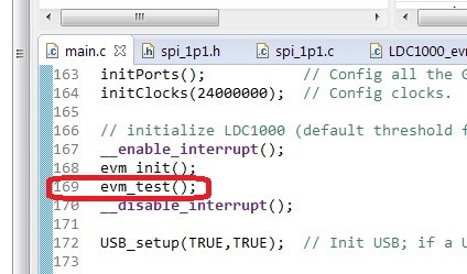
    (1)I used the step over(F6) function to execute code, and find the picture 3 waveform is executing evm_test(); code  in main.c  column 169.

    And the waveform become no signal(picture 4.) when i executing next column code.

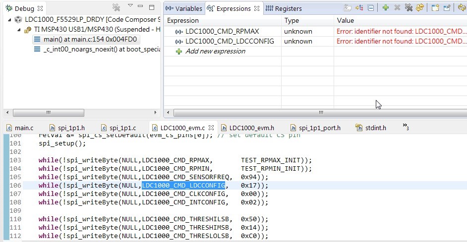
    (2) I can't read any register, it's shows "Error:identifier not found:"   message like picture as below:


    Is something wrong about my procedure ? Should i modify code set up any?  


    BR.

    LEO

  • Hello Lee,

    When you resume the code, what are you trying to do? Are you reading/writing to the register, taking the device out of sleep mode, etc?

    Best Regards,
    Natallia Holubeva
  • Hi, Natallia:

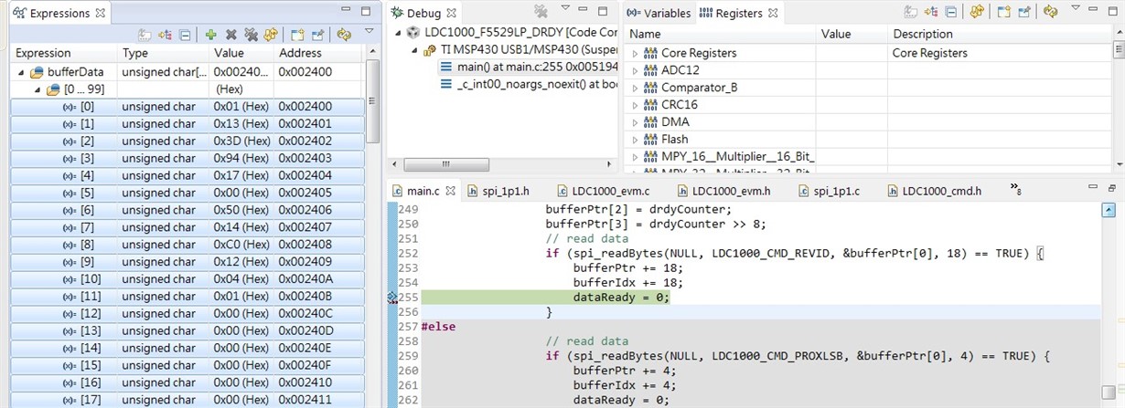
    About read/write LDC1000 registers, please see the picture as below.

    I want to see the LDC1000 18 registers( Device ID to Frequency Counter Data MSB) in datasheet page.14, so i modify LDC1000_F5529LP_DRDY main.c code

    column 252 to 255.

    (1)Is this code modify appropriate(column 252 to 255 )?

    Now i can see the registers(address 0x00~0x0B) appear, but the registers(0x20~0x25) this six registers  data value is zero,no data appear.

    (2)What's wrong with code that i changed? 

    BR.

    LEO

  • Hello Leo,

    You are able to read registers(address 0x20~0x25) but however you are not seeing the data in the right place. You can try the following:


    if (spi_readBytes(NULL, LDC1000_CMD_STATUS, &bufferPtr[0], 6) == TRUE) {

    bufferPtr += 8;

    bufferIdx += 8;

    dataReady = 0;

    }

    (at columns 252 to 255)

    This basically reads 6 bytes of data starting from address 0x20 ( LDC1000_CMD_STATUS), i.e 0x20 to 0x25.

    Now you will be able to read registers(address 0x20~0x25) at bufferData[0] to bufferData[5]. You can put a break point like before and check if you can read it. Let me know if this clarifies your doubt.

    Please let me know if you have other questions.

    -Best Regards,

     Suhas R C

  • Hi, Suhas R C:

    Thank you for your reply.

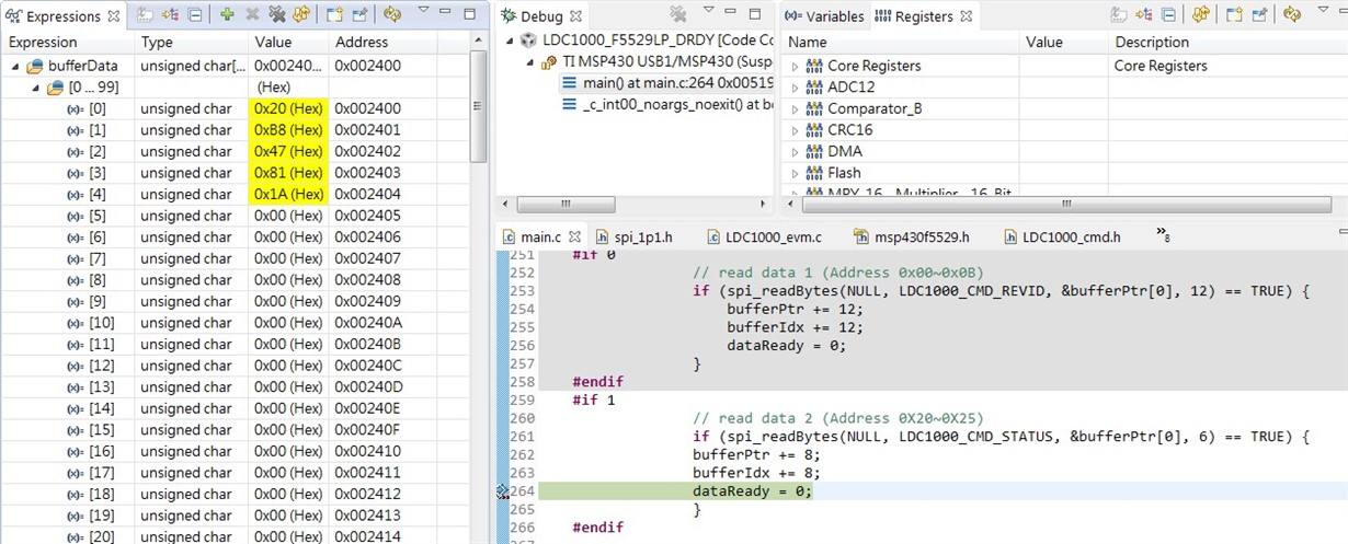
    Now i can read registers (0x20~0x25), like picture as below:

    And i want to ask you two questions:

    (1) LDC1000_CMD_FREQCTRMSB (0x25) bufferData[5]  is no data change, it means the Frequency counter data is 0x001A81 ?

    (2) So i can't read all registers at once, need to separate readout (0x00~0x0B and 0x20~0x25) twice?

    thanks,

    BR,

    LEO.

  • Hello Leo,

    That is great!

    (1) Yes, it says the Frequency counter data is 0x001A81.

    (2) You can read all the registers at once but you need to alter the way you save the data in variable "bufferData". You can try the following in columns 253 to 265 :

    if (spi_readBytes(NULL, LDC1000_CMD_REVID, &bufferPtr[0], 12) == TRUE) {

    bufferPtr += 8;

    bufferIdx += 8;

    dataReady = 0;

    }

    if (spi_readBytes(NULL, LDC1000_CMD_STATUS, &bufferPtr[12], 6) == TRUE) {

    bufferPtr += 8;

    bufferIdx += 8;

    dataReady = 0;

    }

    Now, you will be able to read all the registers at once. You can put a break point in the 2nd "if" statement, read the values and verify it.

    You were not able to read all register values at once earlier as you were overwriting the previously obtained register values.

    Please let me know if this solves your problem.

    -Best Regards,

     Suhas R C


  • Hi, Suhas:

    Ok ,now i can read all the registers at once.

    Thank you for your great help.

    BR,

    LEO .

  • Hello Leo,

    Glad that fixed your problem.

    Let me know if you have any other questions.

    -Best Regards,

     Suhas R C