This thread has been locked.

If you have a related question, please click the "Ask a related question" button in the top right corner. The newly created question will be automatically linked to this question.

LDC1000-Q1 - Zeroes in Proximity Register

Other Parts Discussed in Thread: LDC1101

Hello Team,

We conducted an experiment with a COIL and Rp min/max configuration, so that we can overflow the proximity data. While reading the value of "128" there are single cases when the values goes from 128 to 0 and then immediately back to 128.

What could be the reason for this behavior ?

Regards,

Varban

  • Hello Varban,

    In LDC1000-Q1, Rp value can be dynamically scaled by using Rpmin and Rpmax settings. What were the values for Rpmin and Rpmax in your case?

    When you were reading the proximity data, was the target moving? If that is true, what was the change in distance between target and sensor coil?

    Can you please post a picture of this behaviour?

    Thank you.

    -Best Regards,

     Suhas R C

  • Hello Suhas, 

    Here are the values:

    Rp max = 0x11

    Rp min = 0x32

    The metal target was placed intentionally over the coil (it was not moving) in order to get the maximum value in the Proximity MSB register. After "data ready interrupt", my MCU sends the decimal values over the USB<->SCI interface. The console output was the following:

    value=128

    value=128

    value=128

    value=128

    value=128

    value=0

    value=128

    value=128

    value=128

    value=128

    ....

    value=0

    value=128

    ...

    value=128

    and so on...

    What picture do you need exactly - from the physical test environment or something else ?

    Regards,

    Varban

  • Hello Varban,

    The main question is why the code is only 128? It should be on the order of 10,000 for the best operation.
    Can you try to decrease the RpMIN/MAX by a few codes?
  • Hello Evgeny,

    The reason the value is equal to 128 is that we are reading the MSB Proximity register only, which is 8-bit in length.

    I will try another combinations and I will write to you soon.

    Regards,

    Varban

  • HI Varban,

    If the MSB reads 128, then LDc1000 is out of the Rp range and not functioning properly.
    Please try to increase the RpMIN/RpMAX codes until you see something other than 128.
  • Hello,

    It's been a while since I have tested a lot of RpMIN/RpMAX combinations. Here is my next question:

    We have built a PCB for two LDC1000-Q1 IC with identical footprints, power supply rails for 3.3V and 5V, external 8MHz clock source (from an oscillator, instead of a crystal or MCU pin). Both of the LDCs are connected to a coil - and these two coils share identical parameters (or if not 100% identical, with very similar parameters.).

    For our project we need to detect metal objects over the coils by using the Proximity MSB register.

    We always keep the margin between the RpMIN and RpMAX to be 0x24.

    According to a lot of tests conducted with the LDC1000-EVM, the expected values from

    max(hex) min(hex)
    0B 2F
    0C 30
    0D 31

    should be around or equal to the proximity_msb overflow value ( proximity_msb = 128 /decimal/ ).

    Then, by increasing the RpMIN and RpMAX (keeping the 0x24 margin), the proximity_msb value decreases until it reaches a value close to null.

    However, at the values in the range from (0x0B,0x2F) to (0x0E, 0x32), our first LDC1000-Q1 IC reads "128" in proximity_msb and status register indicates "data ready" (behaves according to the results from the LDC1000-EVM kit), while the other one reads "0" in proximity_msb (and status register here does not indicate "data ready").

    The LDC1000, that reads proximity = 128 with DRDY uses a 820pF capacitor for the LC tank.
    The LDC1000, that reads proximity = 0 with no DRDY uses a 560pF capactor for the LC tank.

    We also added a 330pF capacitor in parallel on both ICs, but the result was the same.

    Is there a logical explanation for this behavior ?

    Kind regards,
    Varban
  • Hello Varban,


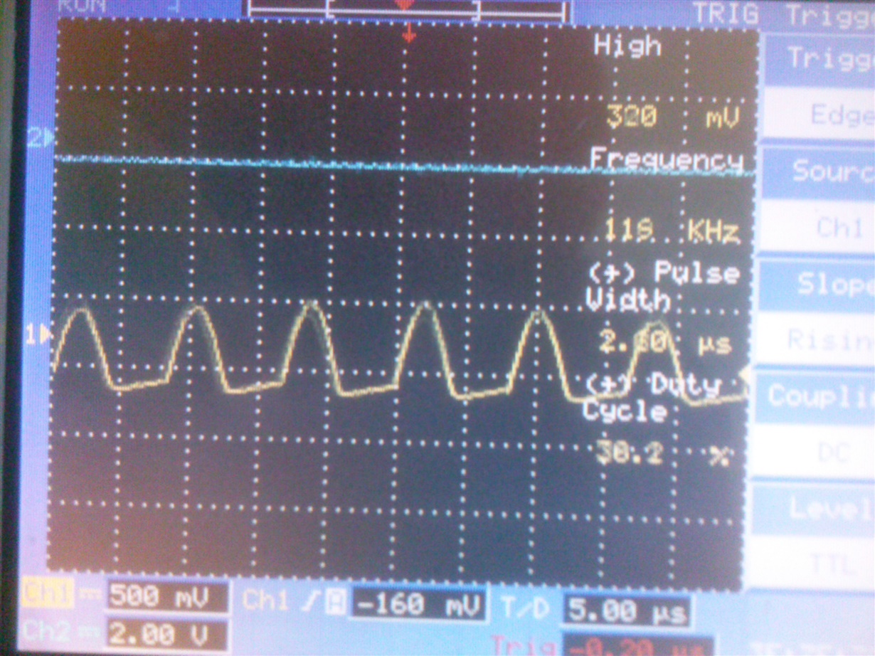
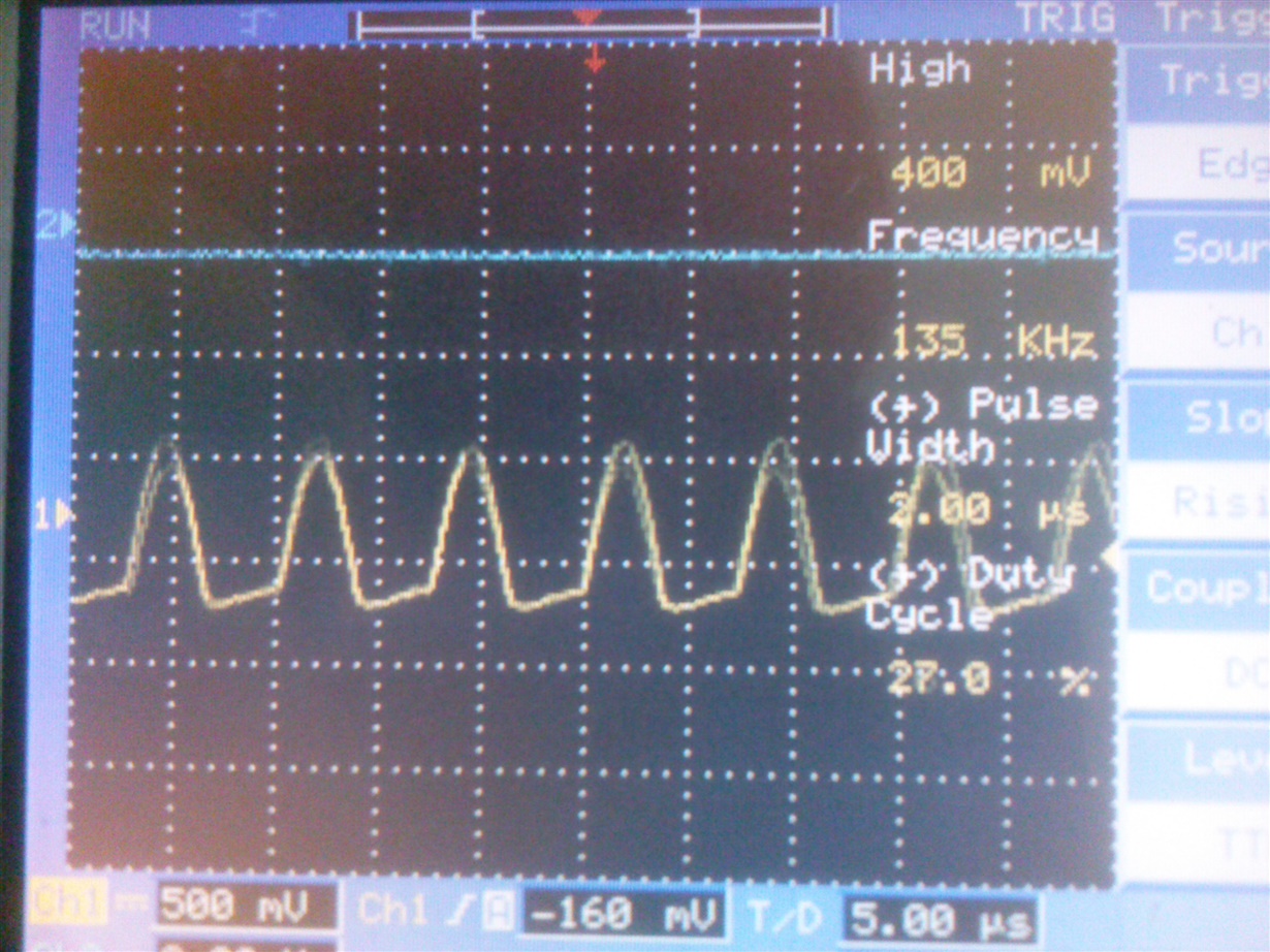
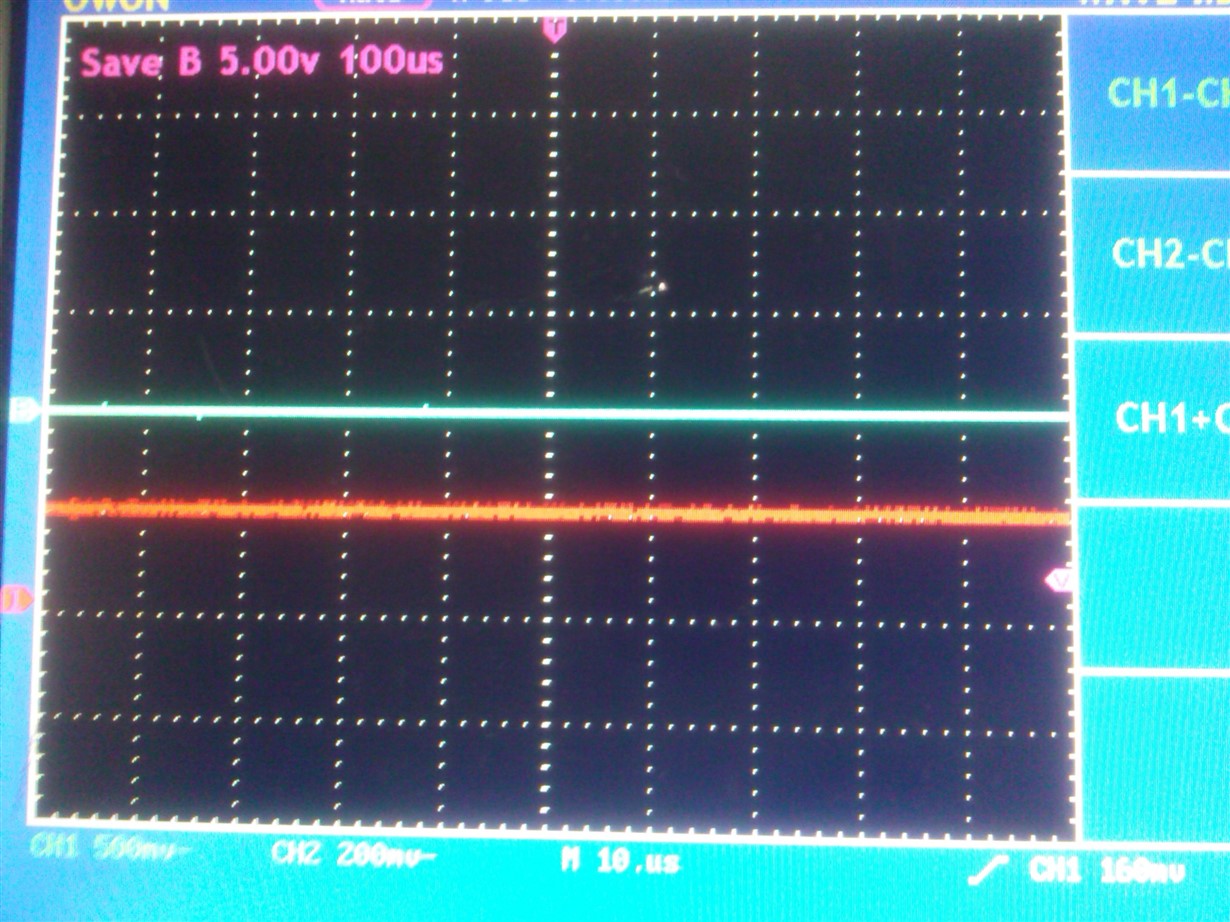
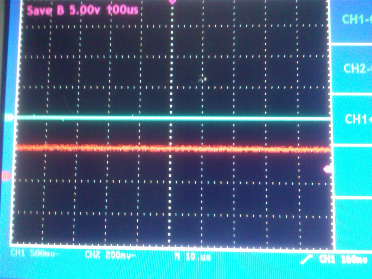
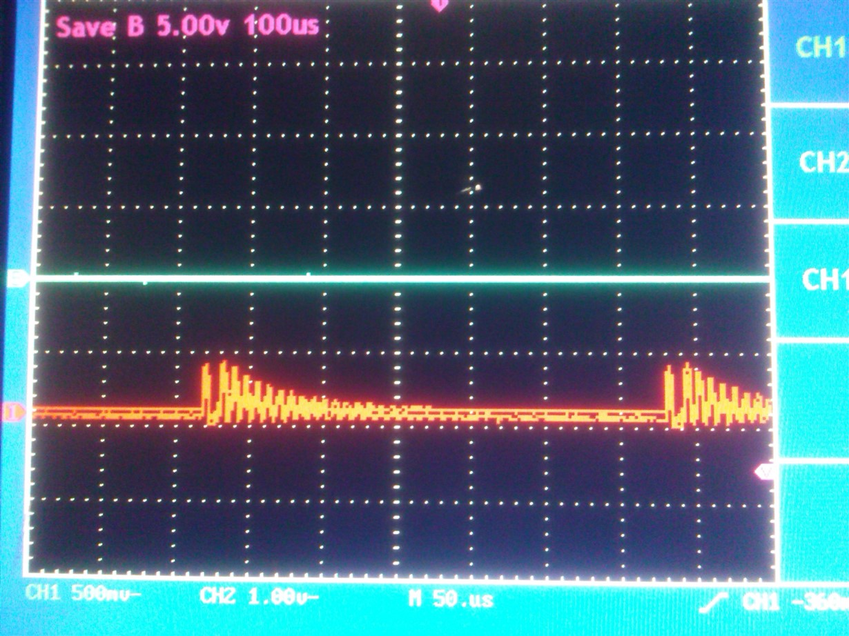
    Can you post INA pin and CFB screenshots for these two ICs?

  • Hello Evgeny,

    Thank you for your fast response! Here are the screenshots you have requested.

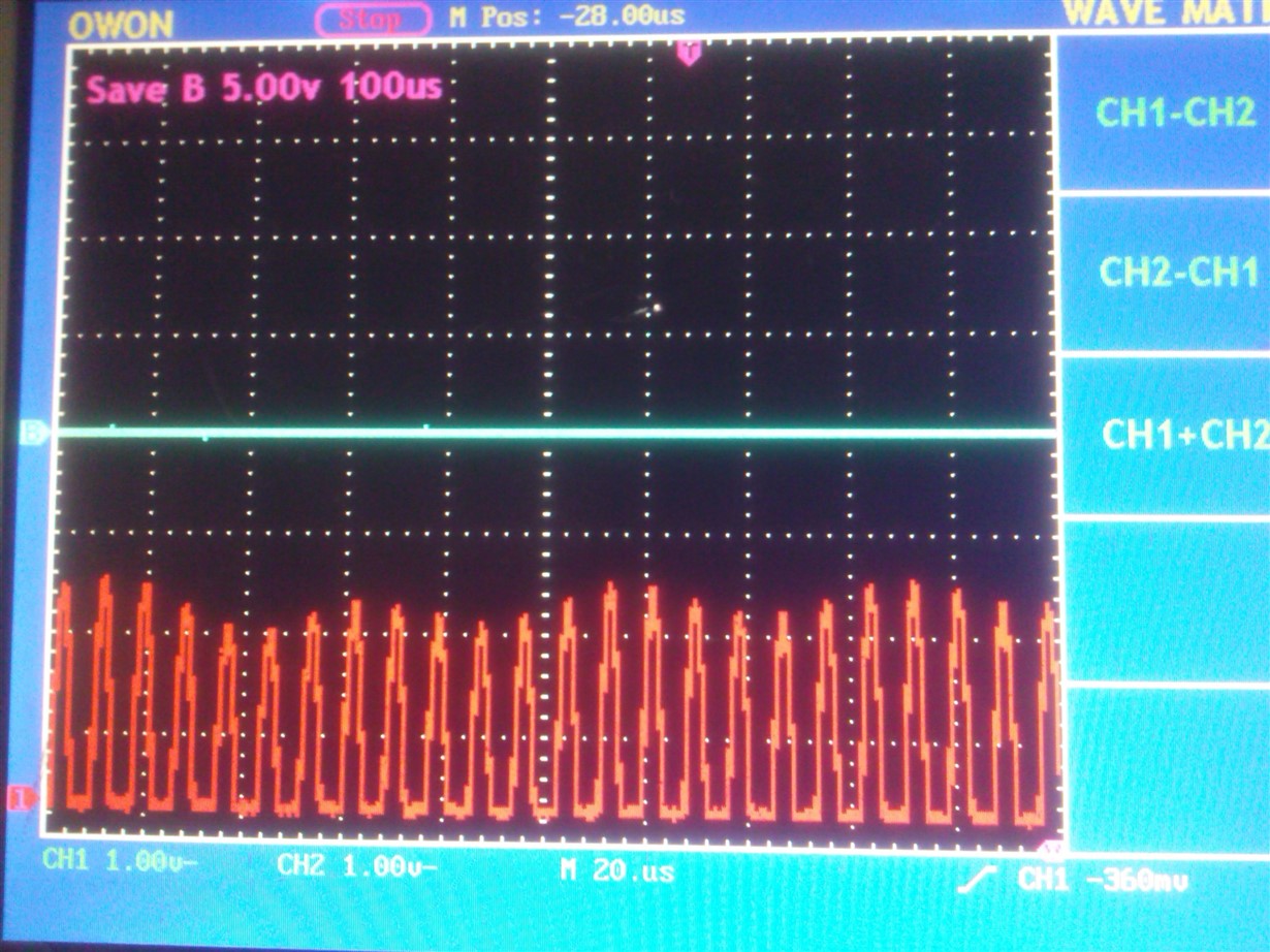
    LDC1000-Q1 IC1, INA:

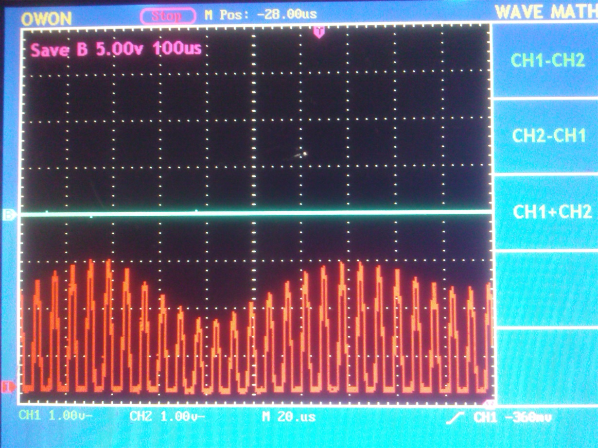
    LDC1000-Q1 IC2, INA:

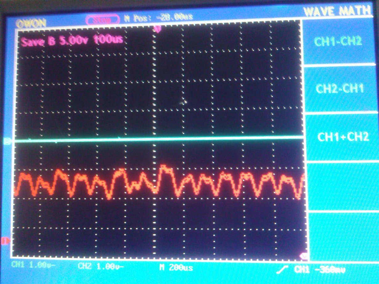
    LDC1000-Q1 IC1, CFB:

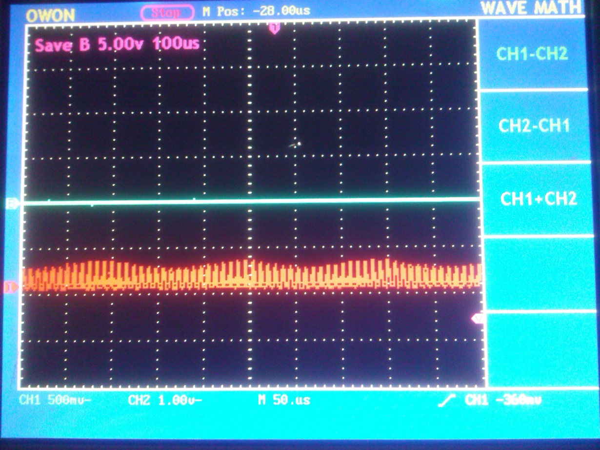
    LDC1000-Q1 IC2, CFB:

    On both of the LDC1000 ICs the measured voltage amplitude was 500mV  (1k resistor was used in series between the pin and the probe for the measurements). 

    The two CFB capacitors are 10nF (0603 package).

    Kind regards,

    Varban

  • Hello Varban,

    A couple of things:

    1) When taking these screenshots, please use the time scale such that you can see an envelope riding on the sine wave. Usually it goes from 2.5V to 4V. Seeing a time scale (hidden in the above shots) would help me to provide recommendation.

    2.CF values are incorrect - there's no oscillations at all. Please follow the procedure from the DS to adjust CF values.

  • Hello Evgeny,

    Thank you for your help.

    About the first point: Could you possibly send me a sample screenshot with the expected sine wave - I do not understand what you mean by "scale such that you can see an envelope riding on the sine wave" ?

    About the second point: I replaced the 10nF capacitors with 4.7nF ones - the result is still the same - there are no oscillations.

    The two ICs are connected to coils with the following values:

    Coil 1 - 1.375mH, 2.09 Ohm

    Coil 2 - 1.380mH, 17.57 Ohm

    PCB wiring for the IC footprints is according to the example provided in the DS.

    Kind regards,

    Varban

  • Hello Varban,

    The LDC1000 alternates between 2 current drive settings; if you look at multiple cycles of the sensor waveform you will see an envelope. For example, if your sensor frequency is 1MHz, which is a period of 1us, and your scope is looking at a timescale of 50us, then you should see a triangular type envelope on the sensor 1MHz. Please look at figure 4 in www.ti.com/.../snaa221, which shows the envelope Evgeny is referencing.

    Regards,
    ChrisO
  • Hello,

    Here are some screenshots with 560pF and 860pF  capacitors correspondingly between INx pins:

    LCD IC1, 560pF:

    LDC IC2, 860pF:

    We tested with 4,7nF, 10nF and 20nF capacitors for the CFB pin - there were no oscillations. 

    After that we soldered a 120pF capacitor and the result on the CFB pin was the following:

    On both LDC IC1 and LDC IC2 (120pF CFB capacitor):

    Then we removed the INx capacitors and tested with another one - one and the same INx capacitor and one and the same coil for both of the LDCs. Here is what happened to the INA pin amplitude, keeping the CFB capacitors at the value of 120pF:

    *Refer to the update - my next post!

    LDC IC1:

    *Refer to the update - my next post!

    LDC IC2:

    The first IC1 is still problematic - it reads zeroes in the lower ranges, mentioned in a previous post.

    The second one seems to work fine (or least far better than IC1)....

  • Update:


    According to the last to shots, where I mention the amplitude issue - I measured the INx pins with a 1k resistor in series - it seems fine now (looks like the first screenshots, with amplitude leveling between 1-3V )

  • Hello Varban,

    The amplitude in the 1st shot is too low - it has to go all they way to 4V, if such oscillation amplitude is chosen in the register

    2nd and 3rd screenshots look good!

    If you cannot get the amplitude to 4V (The Rp of the system is too low) you can try to decrease oscillation amplitude (Reg. 4)

  • Hello Evgeny,

    Thank you for the information! I have figured out how to adjust the filter capacitors until I get the right oscillation.

    As I was experimenting, it turns out that the INx amplitude is influenced by the RpMIN/RpMAX values. Is that true? And if it is, what should be the dependency between them, since I have a "calibration algorithm" that moves the RpMIN/RpMAX up and down, while keeping the margin between them at the value of 0x24 ?

    Also, how many oscillators does the LDC1000-Q1 contain? As far as I understand,  there is an "internal" one that pumps frequency in the LC tank and an "external" one (an oscillator, resonator or MCU pin) that is used by the frequency counter. And which oscillator is concerned in BIT7 of the Status register (LDC1000-Q1 datasheet, page 23)?

    What conditions should be satisfied in order to get that oscillator "overloaded" and stopped?

    Kind regards,

    Varban

  • Hi Varban.

    First, the appropriate CFB capacitance to use is typically for only 1 setting of RPMIN/RPMAX; changing the values dynamically without a mechanism to change the CFB cap may not produce optimum results.

    The LDC1101 is a newer device which incorporates the CFB capacitor internally; you may be able to use it instead. Note that there is currently no Q grade for the LDC1101.

    The "internal oscillator" is not really an oscillator and simply follows the frequency of the LC sensor and injects energy to sustain the oscillation. If the RPMIN value is greater than the sensor's actual RP, then insufficient energy is injected and the sensor amplitude drops below the desired level. You do not want to underrange the sensor.

    The LDC1000 only has one internal timebase which is used to detect if the sensor has stopped oscillating (this is configured via the MIN Resonating Frequency register setting). This is used to indicate that the sensor has stopped oscillating and is reported in STATUS register bit 7.

    Regards,

    ChrisO
  • Hello Chris,

    Thank you for your help.

    Kind regards,

    Varban