This thread has been locked.

If you have a related question, please click the "Ask a related question" button in the top right corner. The newly created question will be automatically linked to this question.

ldc1614 warmup / drift?

Other Parts Discussed in Thread: LDC1614

Hello,

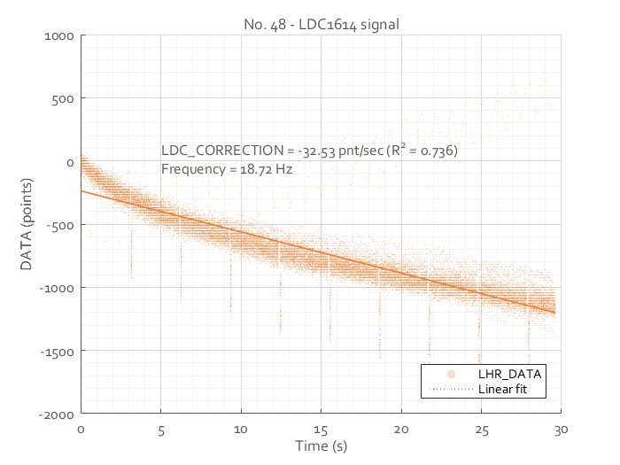
I'm working with the LDC1614 to measure the change in distance between a coil and a aluminum target over time. I've adjusted all settings to get it to give me the most accurate measure for the distance (0.3 - 0.4 mm). I'm taking samples of 30 seconds every 15 minutes and I've noticed some strange behaviour that I hope you could help me explain or correct. I've left the setup on for about 14 hours and plotted the relative change for every 30 seconds, see figure below.

  1. My setup has a datalogger that collects 60 samples before it writes the data to an SD card (that's the faint vertical white stripes every 3-4 second)
  2. Could someone tell me why the signal is slowly decreasing over time? Is this some sort of drift or warmup period?
  3. Could someone explain the slightly lower values for every first measurement that is taken after writing the data to the SD card (that's the faint orange vertical stripes every 3-4 seconds)?
  4. It seems the DATA signal is not completely continues but has steps of 21-22 points (that the white horizontal stripes). That seems like a strange number. If anything I would have expected something like 16 or 32. 

I'm using the following code to get the data:

struct mydata {
    uint32_t    t[60];   // time (s)
    uint32_t    L[60];   // DATA
} collected;

int main( void ){
    while( 1 ) { 

        // collect 60 data points
        for(int i = 0; i < 60; i++) {
            // wait for a new conversion to be ready          
            while( !ldc.is_ready( ) ) {  }

            collected.t[i] = (uint32_t) clock();
            collected.L[i] = ldc.get_Data();
        }

        // write to file
        for(int i = 0; i < 60; i++) {
            fprintf( fp, "%.2f %d\r\n", collected.t[i]/100.0, collected.L[i] ); 
        } 
    }
}

In which ldc is a class with is_ready() reading bit STATUS.DRDY and get_Data() reading DATA_MSB_CH0.DATA0 and DATA_LSB_CH0.DATA0.

I'm looking forward to your reaction.

Thank you, 

Bob Giesberts

  • Hello Bob,

    the drift that you are seeing is most likely caused by slight temperature variations in the room, which affect the value of your sensor capacitor and possibly also expand the metal target so that the target distance changes by a few microns. Please make sure you are using a C0G/NP0 type sensor capacitor to reduce temperature effects on the sensor. Your plot shows a drift of 1500 codes, which is small compared to the 2^28 codes, but need to be taken into account when determining the SNR of the system. I recommend evaluating the system (by simulation or measurement) over the operating temperature to determine the highest code delta due to temperature, and compare it with the signal (move metal from closest to farthest position). If temperature effects exceed your system accuracy specs, you may need a way of compensating for it, such as adding an environmental (reference) coil or a temperature sensor. However, this is typically only required in very high accuracy systems.

    As you noticed, the step change is greater than the LSB of the data converter. It varies with clocking, sensor frequency, and device setup. You can find details in this apps note: http://www.ti.com/lit/an/snoa944/snoa944.pdf 

  • Dear Ben,

    Thank you very much for your quick response and thank you for the link to the app note. I've been using a sensor of 6.5 MHz so I guess I should change this into a 1 MHz one for a higher resolution.

    I don’t think I can agree with your suggestion that this behavior is caused by temperature changes. I'm using a C0G/NP0 capacitor, my setup is in a closed box with a relatively constant temperature and I'm using a thermometer already to compensate for thermal drift over longer periods of time. It is highly unlikely that over a period of 14 hours during each of the 56 measurements of 30 seconds the temperature changed in the same way. Indeed, the same plot for the temperature shows flat lines so this cannot be it. Please have a closer look at the image of my original post, it's not just one measurement, it's the combination of 56.

    What else could have caused this decrease?

    Thank you,

    Bob
  • Hello Bob,
    I put some numbers into a spreadsheet to determine what the maximum drift due to capacitor tempco is. Your setup will of course be very different, but I want to ensure that we're in the same ballpark.
    Let's assume a 14mm coil (figure 72 in this doc www.ti.com/.../snou135a.pdf ) and a 1.6mm thick aluminum target at a target distance of 1mm. A C0G/NP0 sensor capacitor of 330pF is chosen. According to capacitor spec, 1 degree C variation could change the capacitance by up to 30ppm (worst case). With a 40MHz external clock input, this would result in an output code change from 16226513 to 16226026, or 487 codes delta.

    Here are some factors that are different between your setup and my calculation, and could lead to a higher or lower degree of drift:
    - Different sensor design, target distance, target material/size have different tempco.
    - Your temperature variation may be more or less than 1 degree C.
    - I ignored expansion of the metal in my calculation (expected to be small compared to C tempco)
    - I used the worst case tempco datasheet spec for C0G/NP0 capacitors. In real life, they behave much better.
    - I ignored any potential clock drift over temperature.

    The calculation shows that even with a fairly accurately controlled temperature environment, there can be some drift. However, in my example the effect of the drift was quite small; at 1mm target distance, I was seeing 3041 codes per um of target distance change, so a 487 codes delta causes a 160nm measurement error. I could have reduced the error by using a second coil to track environmental changes such as temperature. 

  • Thanks again for your help. Could you tell me what your spreadsheet says when you use my specs?

    6 mm 5 uH coil

    120 pF NP0 capacitor

    40 MHz crystal

    0.3 mm Aluminum (ø 10 mm)

    0.3 mm min distance

    0.5 mm max distance

    Again, I highly doubt that the temperature will change at all over the course of 30 seconds. Let alone having that same temperature change 56x in a row.

    Thanks for helping me out.

    Bob

  • Hello Bob,
    I'm afraid my spreadsheet isn't fully able to work this out based on your test conditions. More measurements or simulations would be required.
    Here is the procedure that I followed:
    - I used real LDC measurement data in 100um steps. I interpolated the data to get the number of codes/um in the region of interest (1mm target distance in my example).
    - I based my calculation on a nominal capacitor value of 330pF. To this capacitance, I added +/-30ppm/degree C to find the min and the max sensor capacitance over a 1 degree C temperature change.
    - I plugged the min/max capacitance back into the equation to calculate the new worst case output code change that changing the temperature by one degree can cause.

    You should be able to use the same approach to estimate worst case temperature drift if you use your codes/um value (from measurement or simulation) and your expected maximum temperature range.

    If you are confident that your drift is much greater than what can be explained by temperature effects, I recommend analyzing the reference clock to determine if there is any wander in your reference clock that could explain the drift. The equations in the datasheet allow you to perform a worst-case calculation similar to my analysis if you know the maximum wander that your clock may have.
  • Hello Bob,

    did you find the reason for your drift issue? I'm using a LDC1000 and see a similar behaviour in my data.

    Thank you,

    Frank Benkert

  • Hi Frank,

    Could you describe your application. We have released two generations of LDC parts since the LDC1000 and depending on your application they may be more appropriate.

    Regards,

    Varn.
  • Hi Varn,
    our application uses an LDC1000, the tank is build by an SMD inductor with 470µH and a C0G, 68pF, 50Vdc capacitor.
    What we see is a small drift of 10 to 30 LSB in proximity signal when keeping the temperature constant.
    Regards
    Frank
  • Hi Frank,

    I think you post got buried since this is an old thread. It's always a good idea to start a new post for a new query and provide a link to the old post.

    Please refer to the following discussion which involves a similar issue, Giacomo and Torben have some very good suggestion regarding debugging a system that shows temp drift. 

    Other than the what is mentioned in this post another source of error in the LDC1000 can be the external oscillator drift. But 10 LSBs of drift is a lot could you reconfirm these numbers?

    Regards,

    Varn