This thread has been locked.

If you have a related question, please click the "Ask a related question" button in the top right corner. The newly created question will be automatically linked to this question.

LDC2114EVM: Test of Button-Press

Part Number: LDC2114EVM
Other Parts Discussed in Thread: LDC1612EVM, LDC2114, LDCCOILEVM, LDC1612

Hello,

I want to test a button-press with the LDC2114EVM over the "Sensing solution EVM GUI".
I want to press the button in a distance of 5-10mm.
As button, i use the contact-plate of a switch.
As inductance, i use a 5mm diameter - PCB-Coil.

My Problem: The LDC only response, when metal is directly put on the coil. And does not detect the deflection, when i press the button.

With the LDC1612EVM, all works fine

Is there any configuartion to set? 

Hope you can help me.

Thanks,
Best Regards,
Marcel Kaufmann

  • Hello Marcel,

    You will need to tune the device configuration for your setup, primarily the GAIN settings. Please refer to the datasheet for a full list of the settings. 

    We additionally have a design calculator tool which helps you optimize the other register settings. Refer to the "LDC2114_Config_tool" tab of the excel calculator tool: http://www.ti.com/lit/zip/slyc137 

    Additionally, please check out our application notes where we go into great detail on optimizing performance:

    LDC Application notes: http://www.ti.com/lsds/ti/sensing-products/inductive-sensing/inductive-sensing-technical-documents.page?familyId=3244&docCategoryId=1 

    Regards,

    Luke

  • Hello Luke,

    Thanks for the answer. 

    Can you probably try tell me, how i should configure the device?

    I already tried to tune the GAIN and other register settings, but it didn´t seem to work.

    Thanks,

    Best Regards,

    Marcel 

  • Hello Marcel,
    The other settings (CNTSC, LC_DIVIDER, etc) need to also be properly set. The easiest way to set these is through the calculator that I attached in the previous post. It suggests the recommended starting values based on the sensor you've attached and its characteristics. Additionally a detailed walk through of the settings including an example is provided in the datasheet, starting on page 28.
    Regards,
    Luke
  • Hello Luke,

    I´m still working on the problem. And have still no solution.

    I want to simulate a simple button with an 1mm spacer inbetween with a 5mm PCB-Coil.

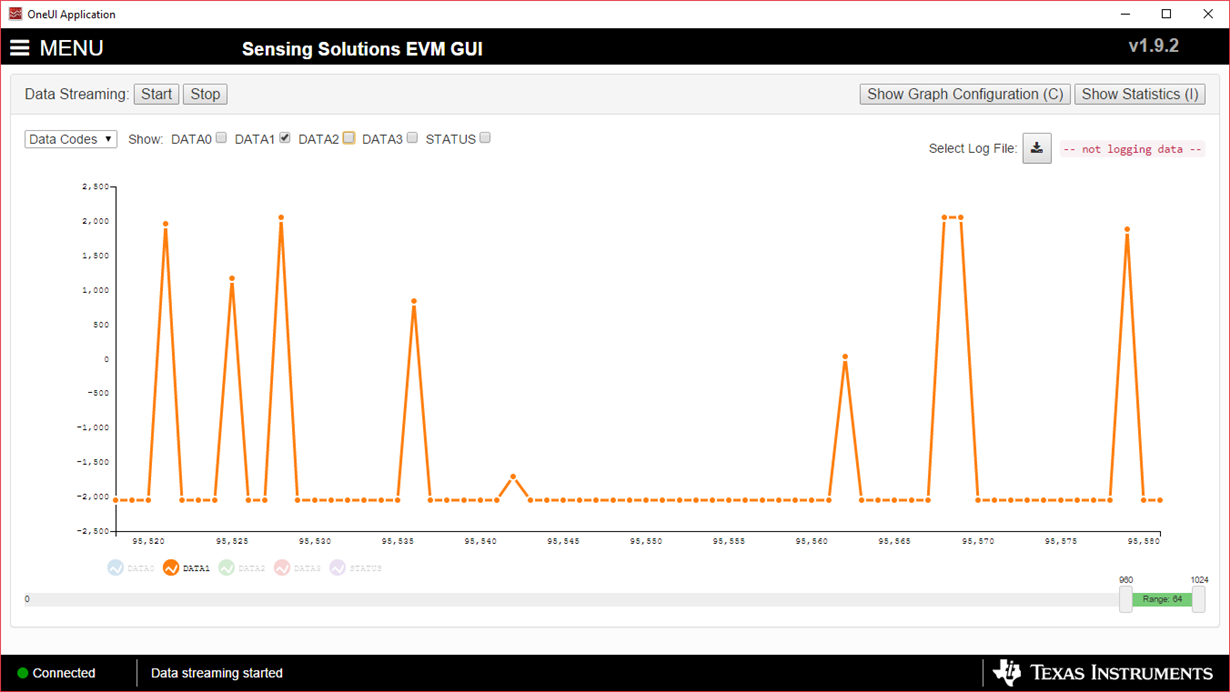
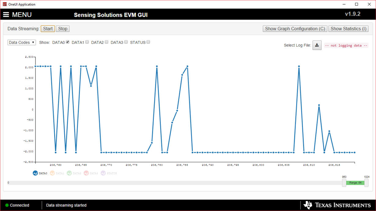
    BUt i only get this all the time, and when i press nothing happens:

    Have you any idea?

    Thanks.

    Regards,

    Marcel

  • Hello Marcel,
    It sounds like some of the settings are not set properly, most likely LCDIV and CNTSC. Can you please share the sensor parameters you've designed? The sensor resonant impedance (Rp) , and sensor resonant frequency (f) for the coil will be required to enter the correct values.
    Thanks,
    Luke LaPointe

  • Hello Luke,

    What do you mean? I use the 5mm - diameter coil from your LDCCOILEVM, with an 330pF - Capacitor.

    Regards,

    Marcel 

  • Hello Marcel,

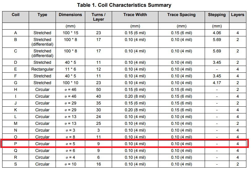
    It sounds like you are using coil P from the LDCCOILEVM which has an outer diameter of 5mm.

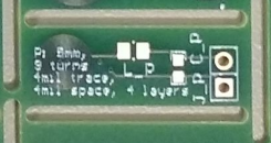
    If this is the case, there is one important thing to note, which is that coil_P has a footprint (L_P) that requires either a 0Ω resistor or a series inductance to complete the circuit.

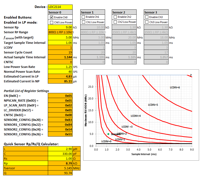
    Assuming that you place a 0Ω resistor for L_P and 330pF for C_P, then your expected oscillation frequency will be around 5MHz. Also note the RP is around 9kΩ. Entering these values into the LDC2114_Config_Tool spreadsheet (www.ti.com/.../slyc137)

    These are the settings I would start with and then tune the gain for your desired sensitivity. If you want detailed guidance on this topic, then refer to the following application note:

    Regards,

    Luke LaPointe

  • Hello Luke,

    Thanks for the information. Now i have made the settings, you suggested and have played with the gain settings, but still get no solution with my button

    Regards,

    Marcel 

  • Hello Marcel,
    Can you explain more about what problem you are now seeing? What do you mean when you say that you get no solution with your button?
    Also can you take an oscilloscope capture of the signals on the IN0 pin? It will be helpful to determine whether the sensor is properly oscillating and setup properly.
    Thank you,
    Luke

  • Hello Luke,

    Now, that i made the settings you recommended, the sensor reacts to metal and when i press the button it works sometimes, but then i get things like this:

    the sensor get crazy. i don´t get any reliable results.

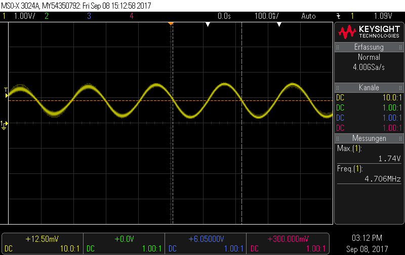
    I think the oszillation is set up properly:

    Is it even possible to detect a buttonpress in form of the contact plate of a smd-switch (diameter 5mm) with a distance of 1 to 5 mm?

    Regards,

    Marcel 

  • Hello Marcel,
    Thanks for the oscilloscope capture, it looks like you are indeed oscillating around the predicted 5MHz. Can you additionally zoom out to measure both the sampling window (how long the oscillation is active) and the scan rate (the time period of how often the oscillation is enabled)?
    Now, it's not quite clear what the mechanical stackup is here. It sounds like you are trying to detect a SMD mechanical push button switch which sits at a nominal distance somewhere between 1mm to 5mm away from the sensor. And the sensor you are using i Coil P from the LDCCOILEVM which is itself 5mm. Can you confirm or clarify the arrangement of button, spacer, and sensor for me? Is everything physically stationary? Or is there loose wires / movement of your setup during the test? Perhaps a photo of your setup or a drawing will also help.
    Additionally, can you confirm what value for gain setting (GAINx) you are using. If you are using a very high value like 63, then you are at the maximum sensitivity and small metal movements can look very large and saturate the signal especially if you have loose wires that are moving around during your test.
    Regards,
    Luke
  • Hello Luke,

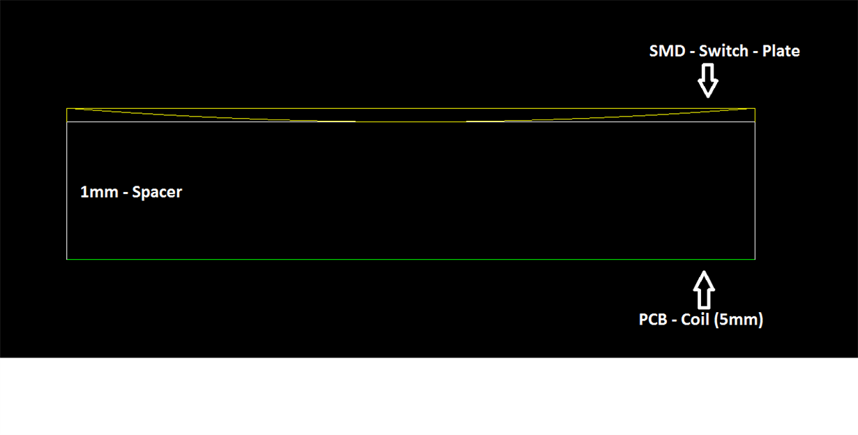
    Yes. I use the Coil P from the LDCCOILEVM with 5mm. Then i place a 1mm - Spacer on the PCB. Then I place the button on the spacer.

    I drew you the rough test - arrangement:

    The plate has a contact travel of approximetaly 250 micrometer (should be enough for the sensor)


    I have another question regarding this topic:

    Isn´t it possible, that the LDC2114 autotune itself like the LDC1612 (with the LDC1612, the test was easy and is working very well, but I want to use the LDC2114 because of its low power consumption)?

    Thanks and kind Regards,

    Marcel

  • Hello,

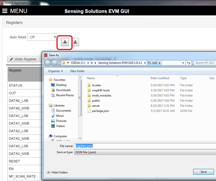
    Thank you for the drawing of your setup. I would still like to confirm that the registers are set properly for this coil. Can you share the register settings? An easy way to do this is to download the registers.json file from the Registers tab of the GUI.

    Thanks!

    Luke

  • Hello,

    Followed, I send you the register settings:

    [[{"idx":0,"id":"STATUS","value":"0x40"},
    {"idx":1,"id":"OUT","value":"0x01"},
    {"idx":2,"id":"DATA0_LSB","value":"0x61"},
    {"idx":3,"id":"DATA0_MSB","value":"0x01"},
    {"idx":4,"id":"DATA1_LSB","value":"0x0"},
    {"idx":5,"id":"DATA1_MSB","value":"0x0"},
    {"idx":6,"id":"DATA2_LSB","value":"0x0"},
    {"idx":7,"id":"DATA2_MSB","value":"0x0"},
    {"idx":8,"id":"DATA3_LSB","value":"0x0"},
    {"idx":9,"id":"DATA3_MSB","value":"0x0"},
    {"idx":10,"id":"RESET","value":"0x00"},
    {"idx":11,"id":"EN","value":"0x01"},
    {"idx":12,"id":"NP_SCAN_RATE","value":"0x01"},
    {"idx":13,"id":"GAIN0","value":"0x19"},
    {"idx":14,"id":"LP_SCAN_RATE","value":"0x02"},
    {"idx":15,"id":"GAIN1","value":"0x3f"},
    {"idx":16,"id":"INTPOL","value":"0x01"},
    {"idx":17,"id":"GAIN2","value":"0x1e"},
    {"idx":18,"id":"LP_BASE_INC","value":"0x04"},
    {"idx":19,"id":"GAIN3","value":"0x1e"},
    {"idx":20,"id":"NP_BASE_INC","value":"0x04"},
    {"idx":21,"id":"MAXWIN","value":"0x00"},
    {"idx":22,"id":"LC_DIVIDER","value":"0x01"},
    {"idx":23,"id":"HYST","value":"0x0d"},
    {"idx":24,"id":"TWIST","value":"0x00"},
    {"idx":25,"id":"COMMON_DEFORM","value":"0x00"},
    {"idx":26,"id":"OPOL","value":"0xff"},
    {"idx":27,"id":"CNTSC","value":"0x00"},
    {"idx":28,"id":"SENSOR0_CONFIG","value":"0xb3"},
    {"idx":29,"id":"SENSOR1_CONFIG","value":"0xb4"},
    {"idx":30,"id":"SENSOR2_CONFIG","value":"0x54"},
    {"idx":31,"id":"FTF0","value":"0x00"},
    {"idx":32,"id":"SENSOR3_CONFIG","value":"0x51"},
    {"idx":33,"id":"FTF1_2","value":"0x00"},
    {"idx":34,"id":"FTF3","value":"0x00"},
    {"idx":35,"id":"MANUFACTURER_ID_LSB","value":"0x49"},
    {"idx":36,"id":"MANUFACTURER_ID_MSB","value":"0x54"},
    {"idx":37,"id":"DEVICE_ID_LSB","value":"0x00"},
    {"idx":38,"id":"DEVICE_ID_MSB","value":"0x20"}]]

    Regarding my other question:

    Have you any information for me about auto-tune for the LDC2114?

    Thanks,

    Marcel

  • Hello Marcel,

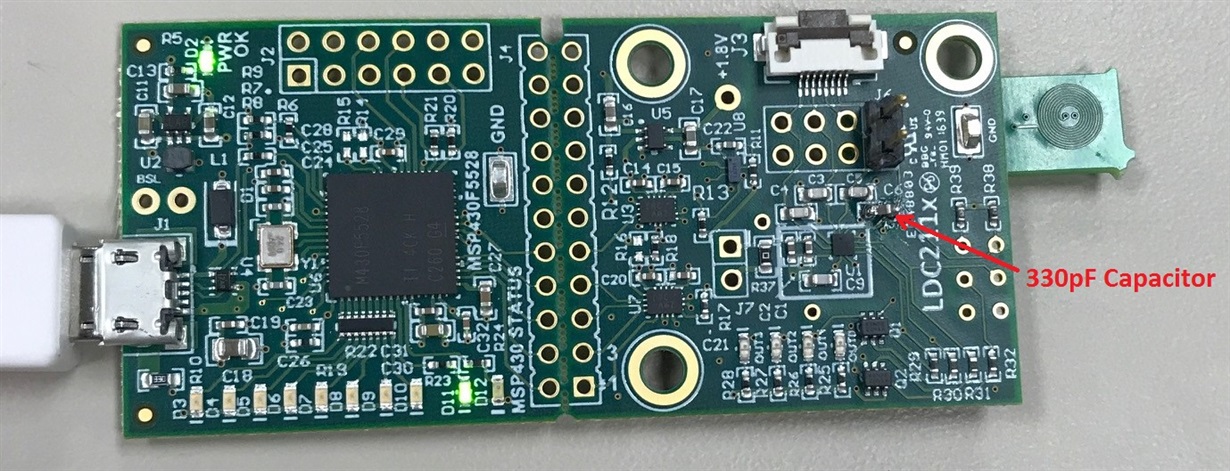
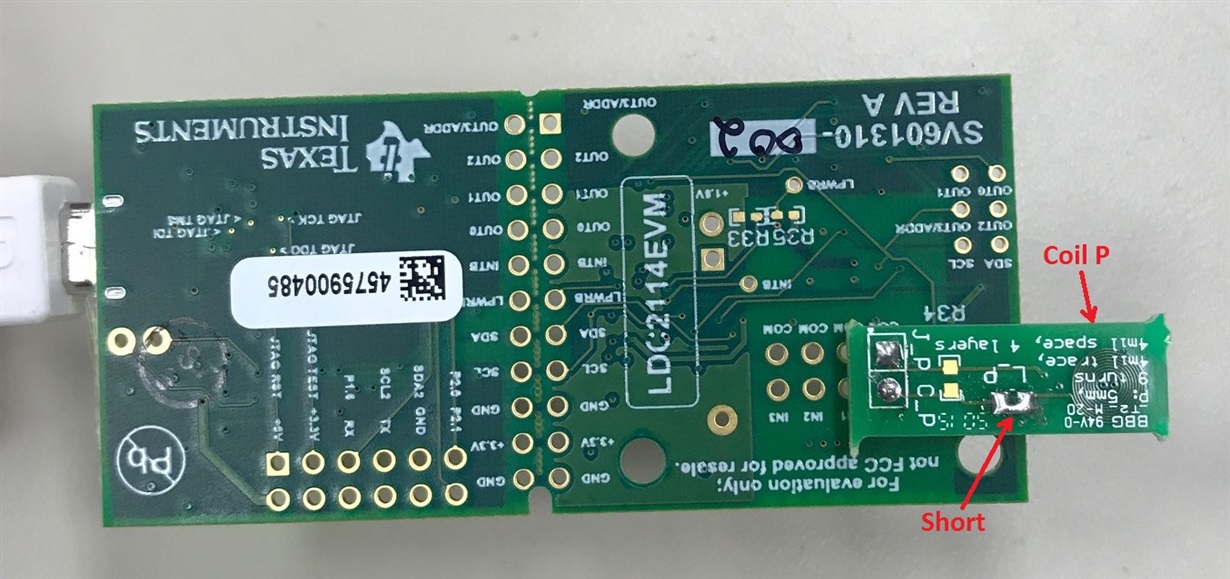
    Thank you for the register file. It seems to match what we had originally suggested. What I've done now is that I've built up the very same configuration that you mentioned, which is LDC2114EVM with Coil P from the LDCCOILEVM and a 330pF capacitor.

    Top View:

    Bottom View:

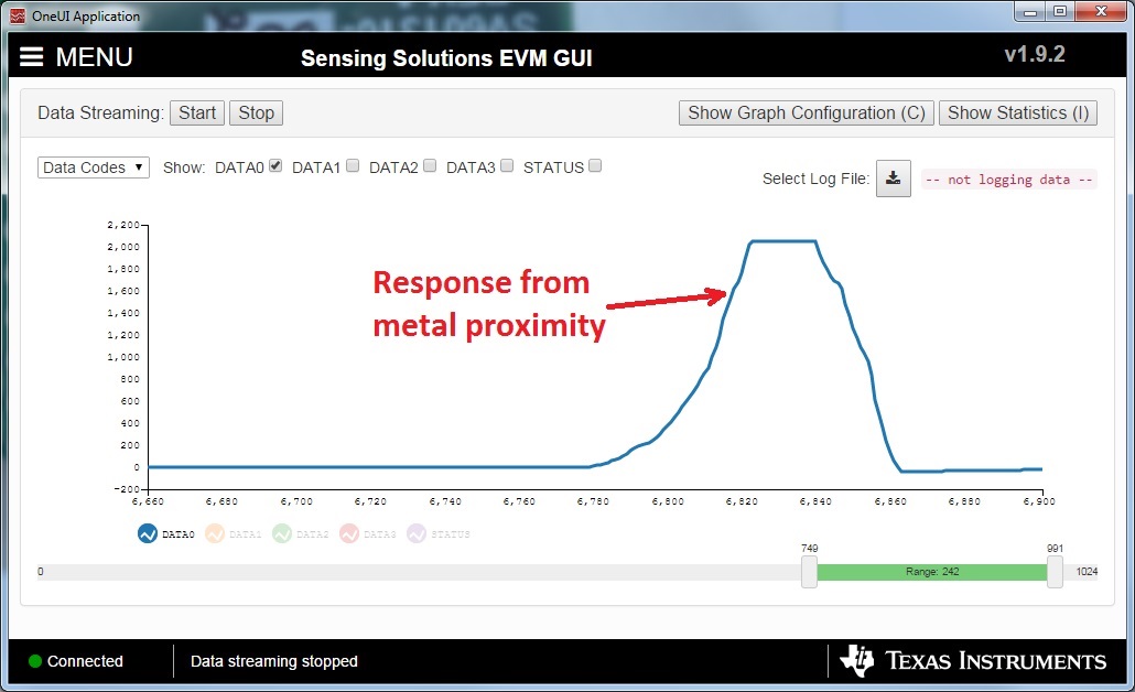
    When I connect it to the GUI and use the configuration listed above I see that the board is working fine and I do not see the large spikes that you are seeing:

    Therefore, I would confirm that all of your connections on your board are soldered well and there is not some loose component or cold solder joint that is giving you strange behavior.

    Regards,

    Luke LaPointe

  • Hello Luke,

    I have completly the same built up as you have, but it didn´t work at all.

    Is it possible, that the demoboard itself have a problem? how can i check it?

    Thanks,

    Regards,
    Marcel
  • Hello Marcel,
    Can you first confirm that the basic functionality is working before you test the button press? Can you test the sensor with no metal present and see if you get these spikes? Then try bringing a piece of metal closer and see if the output changes smoothly? It would be helpful if you datalog the response and upload that here as well.

    Thanks!

    Luke

  • Hello Luke,

    After i updated the firmware of my EVM, all works normal now. 
    The basics works fine and now i´m able to tune the EVM for my application.

    Thank you for your support!

    Regards,

    Marcel

  • Hi Marcel,
    Thanks for the update! I'm glad your EVM is working now.
    Regards,
    Luke