This thread has been locked.

If you have a related question, please click the "Ask a related question" button in the top right corner. The newly created question will be automatically linked to this question.

LDC1000: No DRDY flags on INTB

Part Number: LDC1000

Dear support,

I am using the LDC1000 and have the SPI communication working. I have configured INTB pin Configuration (INTB_MODE) to 0x04 (DRDY). However, the INTB signal always stays high; even when reading from address 0x21 the INTB stays high. When reading from 0x21 there is always 0x00 0x00 returned.
Do you have any idea what could go wrong or what I could try?

Best regards,
Erwin

  • Hello Erwin,

    Have you configured the LDC1000? The default register settings are not valid; and also the default state is Sleep (Standby) mode; which is inactive. Have you put the device into active mode by setting PWR_MODE to 1?

    This type of issue can also occur if the sensor is not oscillating. Try probing the INA pin to ground and check for a triangular sensor signal.

    Another issue can be if the CFB capacitor is not properly set for the sensor and programmed RPMIN/RPMAX settings.

    Finally, the LDC1000 is recommended only for a few very specific applications; generally the LDC1101 is a better choice for most applications, as it has better specs than the LDC1000 (and is also cheaper). Take a look at LDC Selection guide (www.ti.com/.../snoa954.pdf ) if you have not already.

    Regards,
    ChrisO
  • Hello Chris,

    Thanks for you quick reply.

    Yes, I think I configured it right; I wrote all registers to the device and read back to verify. The verify was OK and I definitely have set PWR_MODE to 1. Below I have attached my setting:

    Reg. : Value
    0x00 : 0x80
    0x01 : 0x0D 
    0x02 : 0x33 
    0x03 : 0xB0 
    0x04 : 0x16
    0x05 : 0x00 
    0x06 : 0xFF 
    0x07 : 0xFF
    0x08 : 0x00
    0x09 : 0x00
    0x0A : 0x04
    0x0B : 0x01

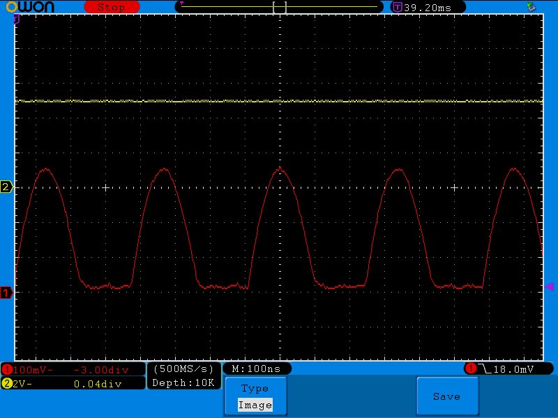
    I have measured the INA signal and attached the screenshot (INA.bmp). The channel 1 in red is the INA signal.

    I am using a ready made board (the LDC1000 click board) so I would assume the hardware should be ok. There is a 22pF

    capacitor between CFA and CFB.

    Best regards,

    Erwin

  • I also have a question on your inductive sensors. what is the max resonant frequency of all your inductive sensors?
    Thanks in advance.
    Best regards,
    David
  • Hi Erwin,

    Please clarify - you scope trace looks like the sensor amplitude is only 350mV; is that correct? If so, then the sensor amplitude is too low. Try changing the RPMIN value from 0x33 to 0x3F.

    Also, can you provide a scopeshot which shows around 50 cycles of the sensor signal?

    Regards,

    ChrisO
  • Hi Chris,

    Thanks for your help. I have changes the register setting to the following: 

    Reg  Value

    0x01 0x11
    0x02 0x3B
    0x03 0xD9
    0x04 0x0F
    0x05 0x02

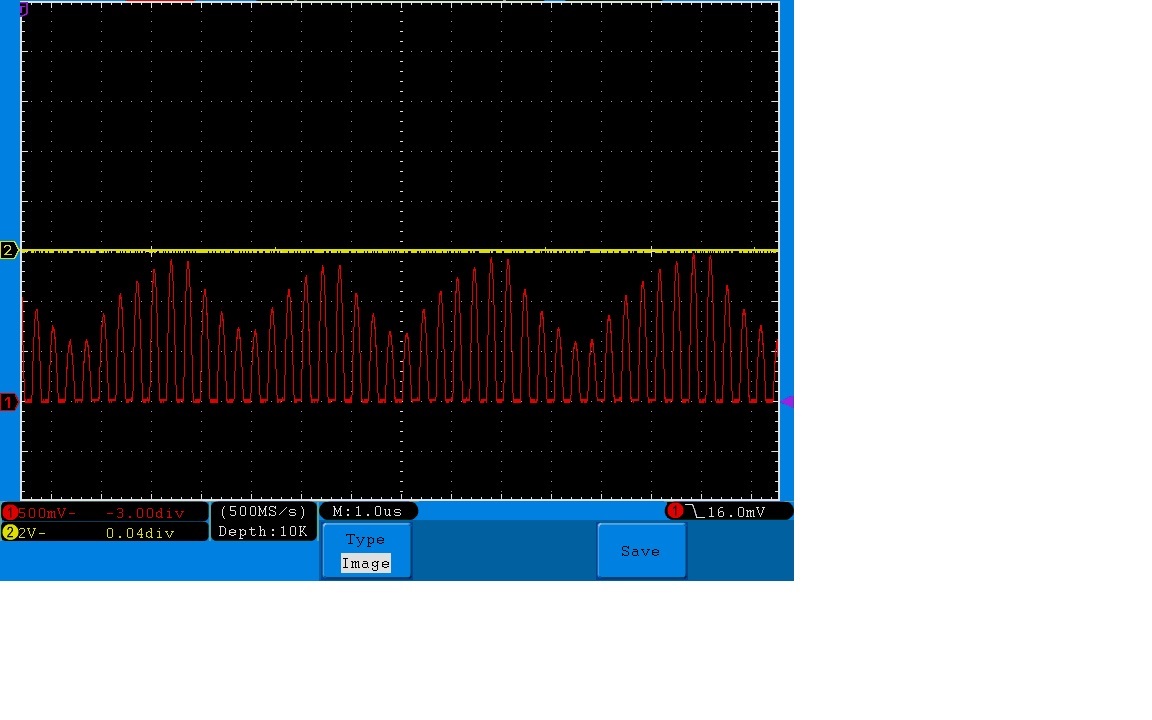
    and now to INTB seems to work. Please find attached the INA signal now with up to 1.5V amplitude; does this look OK?

    Best regards,

    Erwin

  • Hello Erwin,

    Yes, that is the expected signal. The issue you encountered was due to the RPMIN being higher than the sensor's Rp. In that situation, the sensor amplitude is too low.

    You still need to set the CFB capacitor for you RPMIN/RPMAX and sensor settings - look at section 8.1.3 of the datasheet for instructions.

    Regards,

    ChrisO