This thread has been locked.

If you have a related question, please click the "Ask a related question" button in the top right corner. The newly created question will be automatically linked to this question.

LDC1614: Measurement dropouts on LDC1614 four channel mode

Part Number: LDC1614

Dear TI Team,

We´re currently developing on an application using the TI LDC1614 as proximity sensor, whereas the LDC is operated in four channel - sequential mode using a measurement frequency between 1.5 and 2MHz. A highly precise external 40MHz clock is used as reference clock. The LDCs config reads as follows:

CONFIG = 0xDE01

MUX_CONFIG = 0xC20D

R_COUNT = 2400  and R_SETTLE = 96         (same setting applies for all 4 channels -> yields an measurement update frequency of 250Hz)

FIN_DIVIDER = 1, F_REF_DIVIDER = 1          (same setting applies for all 4 channels)

I_DRIVE_CURRENT = 31

Applying those settings yields an analog signal amplitude of approx. 1.6 - 1.7V, what actual complies with the chip requirements. However, the LDC1614 seems sometimes (completely arbitrary behavior) not to be able to excite the oscillation circuit on one or more of the LDC channels. The following figure shows the phenomenon.

The yellow graph indicates a reference signal, the blue graph shows the signal of the LDCs CH0. Obviously the LDC sometimes misses to excite the resonance circuit.

In the course of dissolving the issue we tried to lower the content of the I_DRIVE_CURRENT register (e.g. 28)  -> the signal amplitude drops to ~1.3V and the problem completely vanishes. As we´re not really able to understand this phenomenon we would highly appreciate your expertise related to the problem.

Kind regards,

John

  • HI John,

    Could you provide more information about the sensors that is connected on the four channels? Have you tried enabling the high sensor current drive mode?

    High Current Sensor Drive Mode - The LDC has a high current sensor drive mode (HIGH_CURRENT_DRV) for channel 0 only, which ignores the IDRIVE setting. If RP is so low that an IDRIVE setting of 31 shows an amplitude of less than 1.2 VP , then the current can be boosted by setting HIGH_CURRENT_DRV=1. In this mode, the current drive increases to twice its normal maximum of 1.5 mA in normal mode to 3 mA. This mode is useful for applications in which very small sensors with a low RP is connected. Note that AUTOSCAN_EN must be set to 0 (single channel mode).

    Regards,

    Varn.

  • Hi Varn,

    thanks for your quick reply! As we utilize all four channels of the sensor for our application, high current drive in single channel mode is not a real option.
    The Rp value of our sensor in use is > 1 kOhm at 1.5MHz, thus seems to be fine in accordance with the suggestions made within the LDC1614 datasheet. We initially also thought about a too low Rp, but as the amplitude at IDRIVE 31 is still about 1.7V and the form of the analog signal looks reasonable on the scope we excluded this possibility. The weird thing is that the dropout of single measurements just occurs at higher IDRIVE current settings. Reducing the drive current, hence setting the IDRIVE register to a lower value seems to resolve the issue, what seems to be somehow contradictory in our point of view.
  • Hello John,

    A quick observation. If the amplitude is only 1.7V at maximum IDRIVE, then the RP is roughly 0.85kΩ which does drop below the recommended minimum of 1kΩ. Note that by changing the value of IDRIVE you are also changing the effective value of Rp of the system slightly. Additionally, proximity to metal reduces the Rp. So for the maximum values you could be hitting the edge or slightly below. Rp can be approximately using the following formula. RP = πVP ÷( 4*IDRIVE), where VP is the peak voltage you measure and IDRIVE is the value is given by the table below:

    IDRIVEx Register Field Value Nominal Sensor Current (µA)
    0 16
    1 18
    2 20
    3 23
    4 28
    5 32
    6 40
    7 46
    8 52
    9 59
    10 72
    11 82
    12 95
    13 110
    14 127
    15 146
    16 169
    17 195
    18 212
    19 244
    20 297
    21 342
    22 424
    23 489
    24 551
    25 635
    26 763
    27 880
    28 1017
    29 1173
    30 1355
    31 1563

    Regards,

    Luke

  • Hi Luke,

    Thank´s a lot for your detailed answer! Indeed we used the LDC somewhere around the edge of the allowable Rp with our setup. With a lower I_DRIVE value we slightly exceeded the value of 1kOhm in accordance with the formula provided.

    Thus our next intention was to increase the measurement frequency to get a Rp significantly larger 1kOhm in order to obtain a kind of safety margin. To do so we kept our LDC register config and just changed the capacitors within the resonant circuits of the LDC1614 which lead us to a measurement frequency of about 3.17 MHz.

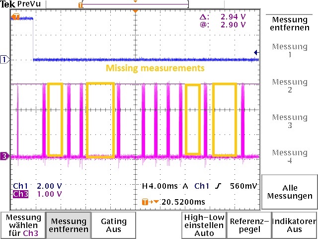
    With an I_DRIVE setting of 31 and a measured Vp of ~2.94V the problem again occured, though we obtain a calculated Rp of 1,477 kOhm.

    (The pink graph shows the analog signal of an affected LDC channel, the orange boxes indicate one or several dropped out measurements)

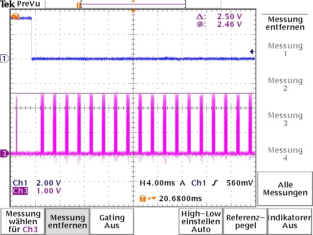
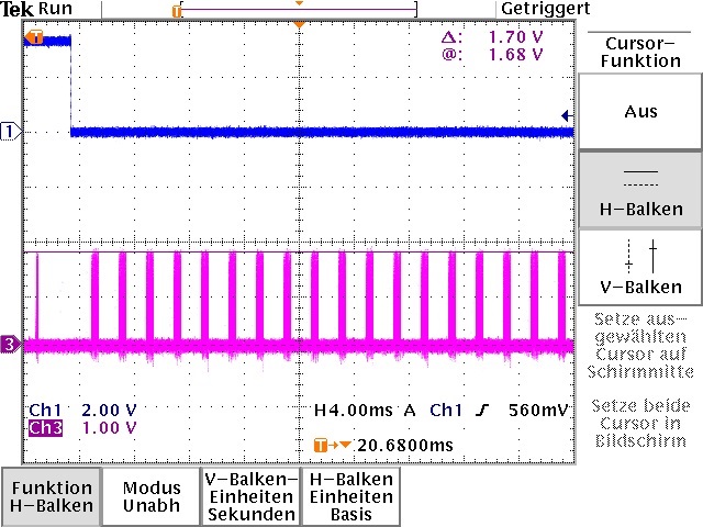
    In the following we again tried to lower the I_DRIVE setting what again made the phenomenon vanish. Two of the tested I_DRIVE settings are shown below:

    1.

    I_DRIVE = 29 lead to a Vp of ~2.50V and to a calculated Rp of 1,67kOhm, this setup worked properly, no dropouts occured.

    2.

    I_DRIVE = 26 lead to a Vp of ~1.70V, to a calculated Rp of 1,75kOhm, this setup worked also properly and again no dropouts occured.

    So also in compliance with the specs, means for us keeping Rp > 1kOhm the chip is obviously not always able to drive the circuit. What seems a little strange, is that the problem more likely shows with a high or even just the highest I_DRIVE setting though more current should be beneficial to excite the resonant circuit.

    Regards,

    John

  • Hello John,
    Keep in mind that we recommend to operate the sensor below 1.8V. If you are going beyond 2V then you start to activate the ESD circuitry of the inputs, so if you're getting 2.94V then this is well beyond the allowable level and would explain the behavior. You can refer to the following document which provides more information on setting the drive current: www.ti.com/.../SNOA950
    Regards,
    Luke
  • Hi Luke,

    thank´s a lot for your advice!! Staying below 2Vp the problem did not occur any more.
    Thus the current issue can from our point of view be marked as resolved.

    Regards,
    John