This thread has been locked.

If you have a related question, please click the "Ask a related question" button in the top right corner. The newly created question will be automatically linked to this question.

AWR1243: ADC samples seem to have a random time rotation

Part Number: AWR1243

Hi everyone,

I seem to have a very strange effect on my board using the AWR1243. It seems that reading data from the LVDS lanes into the PC works fine. When I look at the samples they seem to be quite similar between the antennas - I guess that is ok as the scenario is quite similar for all antennas. However, there is a random shift in the samples. For example when I see a certain "peak" in the time domain, for one antenne it is at the beginning, for one other it is at the end, and a third one has it somwhere in the middle of the stream.

I cannot give much more information as I don't know what may cause that issue. I am not allowed to publish the source code of the project here. I am just askinig for hints where I may have a look at.

I guess I am initalizing the ADC/Lane settings wrong. But is there some miss-configuration where he migh drop bunches of samples? Can I detect if he dropped samples?

It took me quite some time to figure out a "working" configuration if ADC/Lane settings. I am using the COMPLEX_1X mode (2X does not work, what is the difference anyway?). I set the number of samples to 256 in rlProfileCfg_t, but I had to set the number of samples to 512 in radar_setFrameConfig. Why? Is that wrong? The documentation does not seem to make a difference between them.

  • Ohh.. I forgot: More interesting about the "jumping" samples is, that they are different between every measurement. I would expect a more or less constant result (plus noise, ...) over multiple measurements. And I saw this using the evaluation board.
  • Fabian,
    Can you please let us know your configuration:
    ADC Configuration: bits, format, IQ swap
    Datapath configuration, Clock configuration, lane configurations..


    -Raghu
  • Hi,

    I used the configuration from the mmwavelink example project. I attached the configuration file.

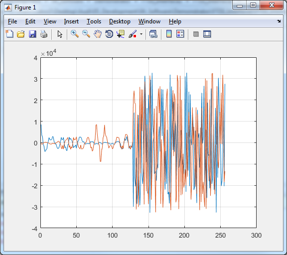
    This also leads to some strange data. I attached a picture of the raw imaginary/real samples coming over the LVDS lanes.

    Best regards,

    Fabian

    mmwaveconfig.txt
    #
    #For detailed view of mmWave Radar configuration structure
    #please refer 
    #ti\control\mmwavelink\docs\doxygen\html\index.html
    #
    
    #
    #cascade mode enable
    #
    cascade_enable=0;
    #END
    
    #
    #power on master arguments, please modify if needed.
    #rlClientCbs_t: crcType, ackTimeout
    #
    crcType=0;
    ackTimeout=1000;
    #END
    
    #
    #channel config parameters, please modify if needed.
    #rlChanCfg_t
    #
    channelTx=3;
    channelRx=15;
    cascading=0;
    #END
    
    #
    #ADC out config parameters, please modify if needed.
    #rlAdcOutCfg_t
    #
    adcBits=2;
    adcFormat=2;
    #END
    
    #
    #DATA format config parameters, please modify if needed.
    #rlDevDataFmtCfg_t
    #
    rxChanEn=15;
    adcBitsD=2;
    adcFmt=1;
    iqSwapSel=0;
    chInterleave=0;
    #END
    
    #
    #Low power config Paramters, please modify if needed.
    #rlLowPowerModeCfg_t
    #
    anaCfg=0;
    lpAdcMode=0;
    #END
    
    #
    #Data Path config parameters, please modify if needed
    #rlDevDataPathCfg_t
    #
    intfSel=1;
    transferFmtPkt0=1;
    transferFmtPkt1=0;
    cqConfig=2;
    #END
    
    #
    #LVDS clock config parameters, please modify if needed
    #rlDevDataPathClkCfg_t
    #
    laneClk=1;
    dataRate=1;
    #END
    
    #
    #SET HSI clock parameters, please modify if needed.
    #rlDevHsiClk_t
    #
    hsiClk=9
    #END
    
    #
    #LANE config parameters, please modify if needed.
    #rlDevLaneEnable_t
    #
    laneEn=15;
    #END
    
    #
    #LVDS Lane Config parameters, please modify if needed.
    #rlDevLvdsLaneCfg_t
    #
    laneFmtMap=0;
    laneParamCfg=1;
    #END
    
    #
    #Profile config parameters, please modify if needed.
    #rlProfileCfg_t
    #
    profileId=0;
    startFreqConst=1435384036;
    idleTimeConst=1000;
    adcStartTimeConst=600;
    rampEndTime=6000;
    txOutPowerBackoffCode=0;
    txPhaseShifter=0;
    freqSlopeConst=621;
    txStartTime=0;
    numAdcSamples=256;
    digOutSampleRate=10000;
    hpfCornerFreq1=0;
    hpfCornerFreq2=0;
    rxGain=30;
    #END
    
    #
    #Chirp Configuration parameters, please modify if needed.
    #rlChirpCfg_t
    #
    chirpStartIdx=0;
    chirpEndIdx=0;
    profileIdCPCFG=0;
    startFreqVar=0;
    freqSlopeVar=0;
    idleTimeVar=0;
    adcStartTimeVar=0;
    txEnable=1;
    #END
    
    #
    #Frame configuration parameters, please modify if needed.
    #rlFrameCfg_t
    #
    chirpStartIdxFCF=0;
    chirpEndIdxFCF=0;
    frameCount=0;
    loopCount=32;
    periodicity=4000000;
    triggerDelay=0;
    numAdcSamples=512;
    triggerSelect=1;
    #END

  • OK, I think I solved the issue with this bad data for the second half of the frame. It seems that it is required to set the number of samples to e.g. 256 for rlProfileCfg_t while setting it to 512 for rlFrameCfg_t. More important I have to choose different ADC formats. When selecting the COMPLEX_2X format for rlAdcOutCfg_t, I have to set it to COMPLEX_1X for rlDevDataFmtCfg_t. I don't see any sense in that.
    However, the problem with the jumping data still exists. It is like the ADCs would trigger at different times.
  • One more update/question: We just figured out that we get similar errors (especially the "random data") with the evaluation board and RadarStudio when we do not connect the RS232. So we sniffed the RS232 data going from the TM4C129 on the AWR1243BOOST to the AWR1243 and found that they are talking a bit in an ASCII manner. What is that? Where is that protocol specified? I thought RS232 connection to the AWR1243 is only required when programming the Flash?

  • Update: I think we solved the problems. We think that this was caused by a bad clock reference signal (aybe too much jitter?). We are not using a crystal directly at the chip and it is working much better.

    However, partially the problem was caused by wrong documentation! The documentation for LVDS we have clains that the first valid bit is on falling edge of the clock signal. That is wrong.

    Never the less, can anyone answer my other questions?

  • Hello fabian,

           Could you point me to this documentation ?

    regards

    AK