This thread has been locked.

If you have a related question, please click the "Ask a related question" button in the top right corner. The newly created question will be automatically linked to this question.

IWR1443BOOST: meaning and functionality of HPF1 and HPF2

Part Number: IWR1443BOOST

Hello,

could you explain a bit more on analog high-pass filters HPF1 and HPF2 from the user point of view?

I understand that the filters included in series after mixer help suppress the low-frequency parasitic Tx-Rx leakage. Then why do you need two filters with pretty high cut-off frequencies? 

That creates a significant blind zone in front of the radar. For example, the minimal corner frequencies of 175 KHz and 350 KHz give me a blind zone up to 92 cm for a sweep of 3.7 GHz 

over 64 microseconds. For longer sweeps and/or smaller bandwidths, i.e. more relaxed sensing, the blind zone only increases which limits target detection in proximity.  Can you suggest a rule

for selection of the two corner frequencies? Thanks a lot in advance.

Regards,

Timofey


  • Hello,

    The analog filters HPF1, and HPF2 are used to attenuate low frequency signals after the receiver mixer, and before the ADC sampling.   

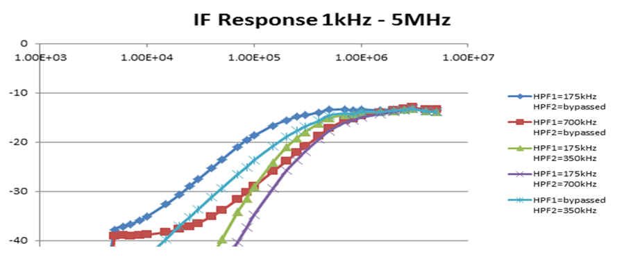
    Normally the 175khz, and 350khz default setting is used.  The attached graphic has some simulated results for the combination of HPF1, and HPF2.

    There is no bypass capability the filters must be used.   Note: when evaluating the radar equations, using the Sensing estimator tool, the maximum range, and range resolution are evaluated.   The min range detected still can be < 1 meter, as the strong return signal, and receiver LNA gain of 24- 48db amplify the Rx signal.

    Regards,

    Joe Quintal

  • Hello,
    As a (practical setting) rule I use the green response of 175khz and 350khz as this has the best low frequency response. The radar return at close in depending on the Radar cross section of the object , Rx LNA of 24, to 48db has been enough for my experiments, however I use the radar with range > 1m. You can use the mmwave capture demo, to collect the Rx complex 1x samples to look at the signal levels.
    Regards,
    Joe Quintal
  • Thank you for the clear answer.