This thread has been locked.

If you have a related question, please click the "Ask a related question" button in the top right corner. The newly created question will be automatically linked to this question.

IWR1443BOOST: TIDEP-0091:level sensing demo: timing measurement

Part Number: IWR1443BOOST
Other Parts Discussed in Thread: TIDEP-0091, IWR1443

I try to use TIDEP-0091(IWR1443BOOST and MSP432). Both boards has been flashed, but output of timing measurement to UART doesn't work.

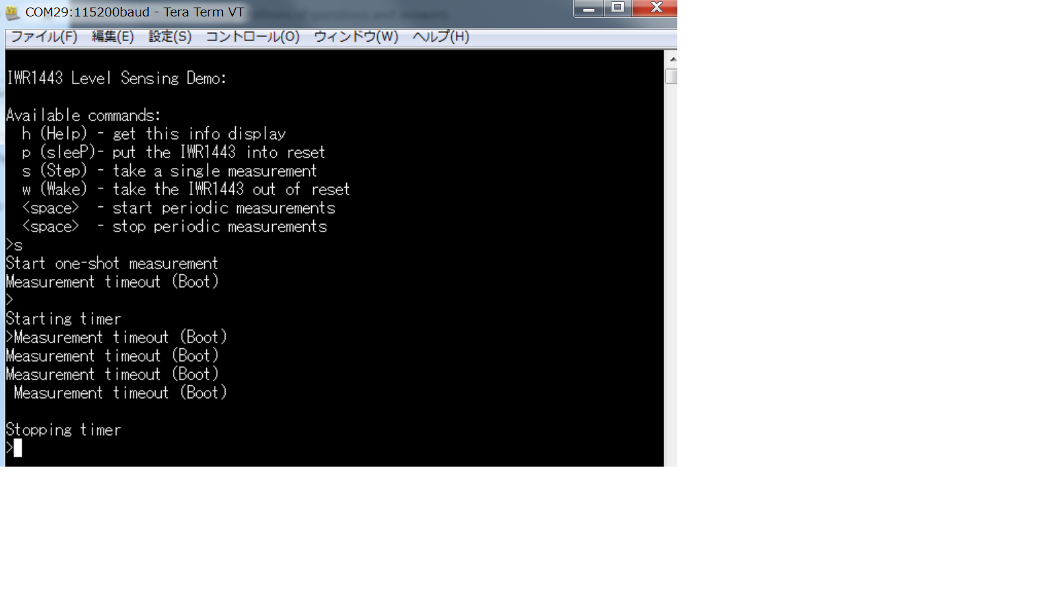
As shown below, "measurement timeout" is displayed on Tera term. 

Could you tell me what is going wrong?

  • Hello Shouhei,

    I need more information in order to answer your question. Are you using the prebuilt binaries or have you modified the code? If you have modified the code would you be able to share what kind of modifications you have made?


    Cheers,
    Akash
  • Thank you for reply, Akash.

    I modified only "demo_common.h" in the folder:level_sense_demo/MSP432, in order to report execution times to UART.
    In particular, I uncommented "#define REPORT_IR14_TIME_MEASUREMENTS".
    In the hardware, 0-Ω resistors were added to R102 and R164 of IWR1443BOOST.

    I want to use the modified code as I wrote above, but
    if I use the prebuilt binaries, does 0-Ω resistor need to be added to R164 or not?
    In the prebuilt binaries, Is "#define REPORT_IR14_TIME_MEASUREMENTS" commented out or uncommented?
  • Hello Akash,

    I do not know if this is related to the problem being consulted,but I will let you know.
    When I build "lsdemo_14xx_mss" in CCS, the following message is displayed in console window.
    "[post-build] Error 216 (ignored)" is displayed, but "lsdemo_14xx_mss.bin" can be generated after build project.

    -----console window-----
    Parsing the input object file, lsdemo_14xx_mss.xer4f.
    Appending zeros 0
    Appending zeros 256
    Appending zeros 59952
    File conversion complete!
    C:/ti/mmwave_sdk_01_01_00_02/packages/scripts/ImageCreator/append_bin_crc/gen_bincrc32.exe lsdemo_14xx_mss.bin
    makefile:196: recipe for target 'post-build' failed
    process_begin: CreateProcess(C:\ti\mmwave_sdk_01_01_00_02\packages\scripts\ImageCreator\append_bin_crc\gen_bincrc32.exe,
    C:/ti/mmwave_sdk_01_01_00_02/packages/scripts/ImageCreator/append_bin_crc/gen_bincrc32.exe lsdemo_14xx_mss.bin, ...) failed.
    make (e=216): Error 216
    gmake[3]: [post-build] Error 216 (ignored)


    **** Build Finished ****
    -------------------------

    Another more,size of prebuild "lsdemo_msp432_m4f.out" is 2861KB,
    but size of "lsdemo_msp432_m4f.out" generated after build "lsdemo_msp432_m4f" is only 2681KB.


    Regards,
    Shouhei
  • The pre-built binaries have  REPORT_IR14_TIME_MEASUREMENTS commented out, so that the IWR1443 will not flip GPIO0 and the MSP432 will not wait to see it.  You should try running these binaries first, to check that the modified hardware is still functioning properly.  Then, you must rebuild *both* IWR1443 and MSP432 executables with the uncommented  REPORT_IR14_TIME_MEASUREMENTS.  If you don't rebuild both and then flash both, the MSP432 will timeout because the GPIO0 activity on the IWR1443 will not match what the MSP432 is expecting.

      -dave

  • Hello,

     To help diagnose the problem, there is a specific sequence for the attached PDF.  

    Measuring the HOST Interrupt, GPIO0, and NRST can be done by attaching oscilloscope probes, and measurments..

    Regards,

    Joe Quintal

    Note: GPIO1 usage is in the final version of the software , to select a CALIBRATION or MEASUREMENT cycle.

    Visio-levelsensing_timingnotes.pdf

  • Thank your reply, Dave

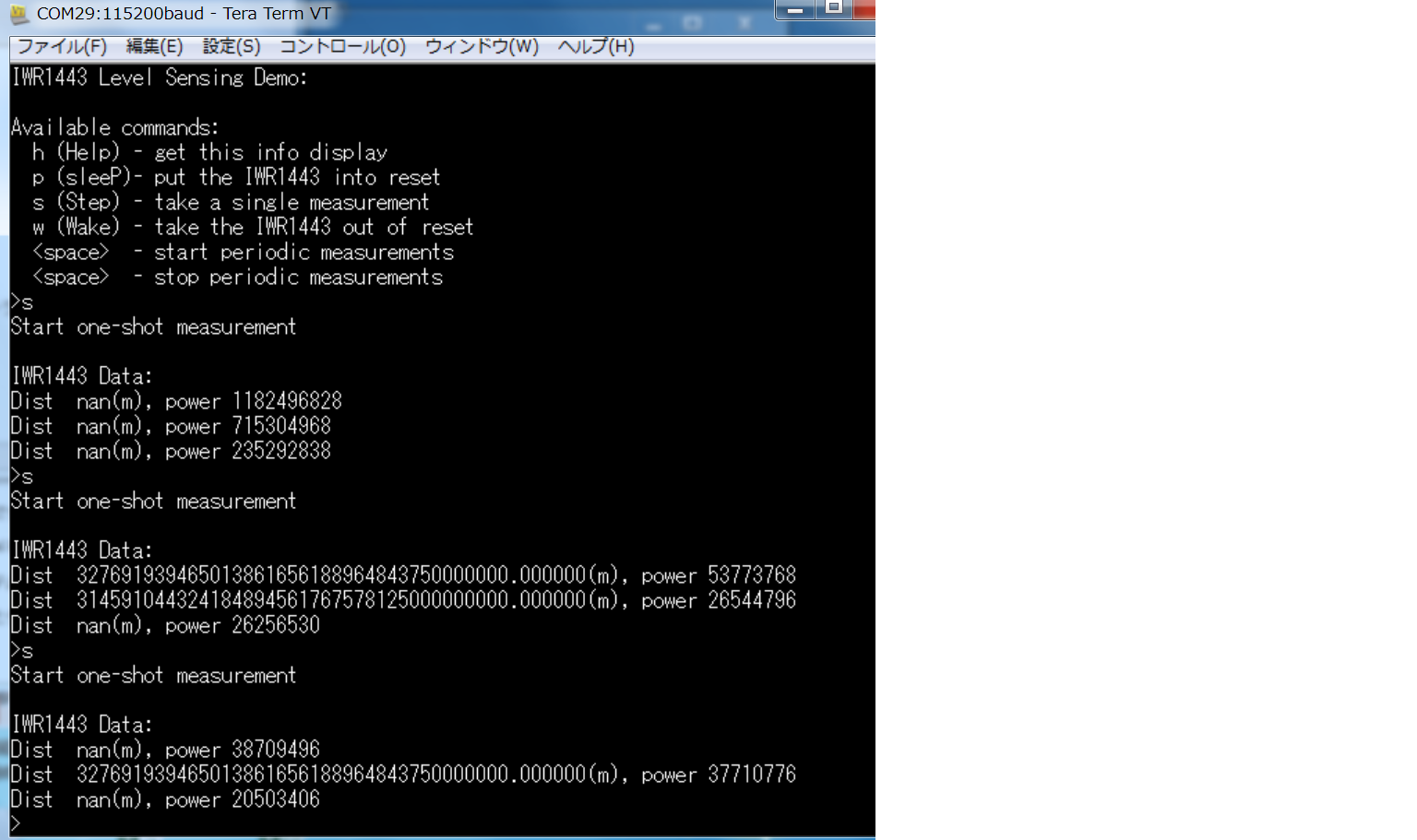
    I tried running pre-built binaries, and a figure shown below is displayed on TeraTerm.
    The number representing the distance is very large,
    As time goes by, the screen gets settled. What is going wrong in the modified hardware?

    Then,I rebuilded both IWR1443 and MSP432 executables with the uncommented REPORT_IR14_TIME_MEASUREMENTS.
    However, "measurement timeout(Boot)" is displayed on Tera term.

    Regards,
    Shouhei

  • Yes, that output is obviously wrong.  I have not seen it look like that.  First, please check that you are using the exact versions of the tools specified on slide 5 (Pre-requisites) of the Getting Started guide.  Use version 1.40 of the MSP432 SimpleLink, do not use version 1.60.  If you have 1.60 installed, uninstall it, install 1.40, then restart CCS and go into the MSP432's project properties and make sure 1.40 is selected.  Do a clean + build.

    Another possibility is that your resistors are not correctly installed.  Please make sure they are on the correct pads, and that no solder is touching adjacent pads.  If you don't see the IWR1443's LEDs turn on and off when you do a single shot, then you know that R102 is not present.

    You can run the demo with no resistors installed (or ignoring the resistors that are installed).  If you follow the instructions in section 5.2 of the Getting Started guide, you can run a single measurement in CCS and see what the measurements are that will be sent to the MSP432 over SPI. This will tell you if the problem is in the 1443, or in the communication with MSP432.

      -dave

  • Thank your reply,Dave.

    I uninstalled 1.6-version and used 1.40-version of the MSP432, but "Measurement timeout(boot)"
    was displayed.
    I can see the IWR1443's LEDs turn on and off when I do a single shot, and so R102 is present.
    I think R164 is present,too.
    Other resistors are not needed?

    Is Mono JIT compiler needed on Windows OS PC?
    Pinmuxtool ,Doxygen and Graphviz are needed in order to do level_sense_demo?
    I don't install these tools,now.

    Regards,
    Shouhei