This thread has been locked.

If you have a related question, please click the "Ask a related question" button in the top right corner. The newly created question will be automatically linked to this question.

AFE4404: Getting troubles with calculating heart rate

Part Number: AFE4404

Hello!

I connected the AFE4404 sensor to the microcontroller, set the registers in accordance with the standard settings (see below). My task is to calculate the heart rate, for this I activate the green LED1 and at 100Hz I get ADC data from register 0x2C for 10 seconds (1024 values).

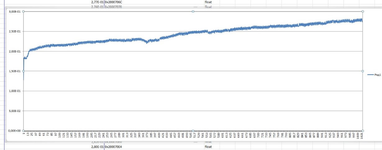
But after converting ADC data, I get only noises (the sensor is leaning against my hand).

What could be the problem?

#define FIELD_SIZE                      32U
#define ADC_DATA_SIZE                   24U
#define ADC_SIGN_FIELD_SIZE             3U
#define ADC_PAYLOAD_FIELD_SIZE          ADC_DATA_SIZE-ADC_SIGN_FIELD_SIZE  //21
#define ADC_SIGN_FIELD_MASK             0x00E00000U
#define ADC_PAYLOAD_FIELD_MASK          0x001FFFFFU
#define SCALE_DIVISION                  1.2/pow(2,21)
#define MAX_ADC_SCALE_RANGE             1.2
#define MIN_ADC_SCALE_RANGE             (-1.2)

#define POL             0x0<<ADC_PAYLOAD_FIELD_SIZE ///Positive and lower than positive full-scale (within full-scale range)    000
#define POL_MASK        0x00000000U
#define POH             0x1<<ADC_PAYLOAD_FIELD_SIZE ///Positive and higher than positive full-scale (outside full-scale range)  001
#define POH_MASK        0x00200000U
#define NEL             0x6<<ADC_PAYLOAD_FIELD_SIZE ///Negative and lower than negative full-scale (outside full-scale range)   110
#define NEL_MASK        0x00C00000U
#define NEH             0x7<<ADC_PAYLOAD_FIELD_SIZE ///Negative and higher than negative full-scale (within full-scale range)   111
#define NEH_MASK        0x00E00000U

float adc_to_float(int32_t field32_t)
{
    field32_t&=~OPTION_BIT_MASK;
    if((field32_t&ADC_SIGN_FIELD_MASK)==POL)
    {
        field32_t&=ADC_PAYLOAD_FIELD_MASK;
        return field32_t*(SCALE_DIVISION);
    }
    else if((field32_t&ADC_SIGN_FIELD_MASK)==POH)     ///outside the scale
        return MAX_ADC_SCALE_RANGE;
    else if((field32_t&ADC_SIGN_FIELD_MASK)==NEL)     ///outside the scale
        return MIN_ADC_SCALE_RANGE;
    else if((field32_t&ADC_SIGN_FIELD_MASK)==NEH)
    {
        field32_t&=ADC_PAYLOAD_FIELD_MASK;
        return field32_t*(-SCALE_DIVISION);
    }
    return 0;
}

void AFE4404_Reg_Init(void)
{
  AFE4404_Reg_Write(0, 0);   // Write enable

  /* RECEIVE-TRANCEIVE TIMING CONFIGURATIONS */
  ///transeive                  |   REG_NAME     |   OPTIM_VALUE |
  AFE4404_Reg_Write(9, 0);      //AFE_LED2LEDSTC        ..0
  AFE4404_Reg_Write(10, 399);   //AFE_LED2LEDENDC       ..398
  ///receive led
  AFE4404_Reg_Write(1, 100);    //AFE_LED2STC           ..100
  AFE4404_Reg_Write(2, 399);    //AFE_LED2ENDC          ..398
  ///receive ambient
  AFE4404_Reg_Write(5, 501);    //AFE_ALED2STC          ..500
  AFE4404_Reg_Write(6, 800);    //AFE_ALED2ENDC         ..798
  ///so on
  AFE4404_Reg_Write(3, 802);    //AFE_LED1LEDSTC        ..800
  AFE4404_Reg_Write(4, 1201);   //AFE_LED1LEDENDC       ..1198
  AFE4404_Reg_Write(7, 902);    //AFE_LED1STC           ..900
  AFE4404_Reg_Write(8, 1201);   //AFE_LED1ENDC          ..1198
  AFE4404_Reg_Write(11, 1303);  //AFE_ALED1STC          ..1300
  AFE4404_Reg_Write(12, 1602);  //AFE_ALED1ENDC         ..1598

  AFE4404_Reg_Write(54, 401);   //AFE_LED3LEDSTC        ..400
  AFE4404_Reg_Write(55, 800);   //AFE_LED3LEDENDC       ..798

  /* CONVERSION TIMING CONFIG */
  AFE4404_Reg_Write(13, 409);   //AFE_LED2CONVST        ..5608
  AFE4404_Reg_Write(14, 1468);  //AFE_LED2CONVEND       ..6067
  AFE4404_Reg_Write(15, 1478);  //AFE_ALED2CONVST       ..6077
  AFE4404_Reg_Write(16, 2537);  //AFE_ALED2CONVEND      ..6536
  AFE4404_Reg_Write(17, 2547);  //AFE_LED1CONVST        ..6546
  AFE4404_Reg_Write(18, 3606);  //AFE_LED1CONVEND       ..7006
  AFE4404_Reg_Write(19, 3616);  //AFE_ALED1CONVST       ..7016
  AFE4404_Reg_Write(20, 4675);  //AFE_ALED1CONVEND      ..7475

  /* START CONVERSION TIMING CONFIG */
  AFE4404_Reg_Write(21, 401);   //AFE_ADCRSTSTCT0       ..5600
  AFE4404_Reg_Write(22, 407);   //AFE_ADCRSTENDCT0      ..5606
  AFE4404_Reg_Write(23, 1470);  //AFE_ADCRSTSTCT1       ..6069
  AFE4404_Reg_Write(24, 1476);  //AFE_ADCRSTENDCT1      ..6075
  AFE4404_Reg_Write(25, 2539);  //AFE_ADCRSTSTCT2       ..6538
  AFE4404_Reg_Write(26, 2545);  //AFE_ADCRSTENDCT2      ..6544
  AFE4404_Reg_Write(27, 3608);  //AFE_ADCRSTSTCT3       ..7008
  AFE4404_Reg_Write(28, 3614);  //AFE_ADCRSTENDCT3      ..7014

  /* PULSE RATE FREQUENCY SCANNING PERIOD */
  AFE4404_Reg_Write(29, 39999); //AFE_PRPCOUNT          ..39999
  AFE4404_Reg_Write(57, 0);      //CLKDIV_PRF

  AFE4404_Reg_Write(30, 0x000103); //AFE_CONTROL1 TimerEN = 1; NUMAV = 3
  AFE4404_Reg_Write(32, 0x008003);  //AFE_TIA_SEP_GAIN (LED2) ENSEPGAIN = 1; LED2/LED3 gain = 50K

  AFE4404_Reg_Write(33, 0x000103);  //AFE_TIA_GAIN (LED1) LED1/LED1AMB gain = 50K ADC_RDY_MANUAL_DURATION_SET_EN

  AFE4404_Reg_Write(58, 0x000000);  //AFE_DAC_SETTING_REG
  AFE4404_Reg_Write(34, 0x0030CF);  //LED3 - 3.125mA; LED2 - 3.125mA; LED1 - 12.5mA <=//default 0x0030CF
  AFE4404_Reg_Write(35, 0x104018);  //DYN1, LEDCurr, DYN2, Ext CLK, DYN3, DYN4 //0x000200); - 0x200 Osc mode //AFE_CONTROL2
  AFE4404_Reg_Write(49, 0x000020);  //ENABLE_INPUT_SHORT

  /* POWER DOWN PERIOD CONFIG */
  AFE4404_Reg_Write(50, 5475);   //AFE_DPD1STC  //PDNCYCLESTC  ..7675
  AFE4404_Reg_Write(51, 39199);  //AFE_DPD1ENDC //PDNCYCLEENDC  ..39199

  /* ADC_RDY_DURATION */
  
  AFE4404_Reg_Write(52, 4700);		//PROG_TG_STC
  AFE4404_Reg_Write(53, 5200);		//PROG_TG_ENDC
  
  //AFE4404_Reg_Write(61, DEC_FACTOR_4);  //decimation enable with corresponding factor
  
  AFE4404_Reg_Write(0, 1);   // Read enable
}

  • Hi Igor,

    I see some kind of noise in the data. This might be due to noise pick from AC mains.
    So can you run your experiment form battery powered device ( such as laptop with charger disconnected).
    Also can you try following things,
    1) Try at finger tip first.
    2) Increase the LEd current or TIA gain. But do not saturate the ADC.
    3) Cover the sensor module so that there is no ambient light going into the module.

    Regards,
    Prabin
  • Hi Prabin,

    I have the same problem like Igor has.
    I did everything that you said above, but it still has a noise.
    Do you have any another idea?
    And, how the graph needs to look?

    Thanks in advance,
    Oshrit
  • Hi Oshrit,

    You can refer to figure 8 of following document for the sample PPG waveform.
    www.ti.com/.../slau621a.pdf

    Did you try with the default register setting from the AFE4404EVM?

    Regards,
    Prabin
  • Hi Prabin,

    Thanks for your quick answer!

    I using an ST EVB and I connect it to IT's EVB (AFE4404). Therefore, I cannot use the  AFE4404 EVM GUI to see the waveform.

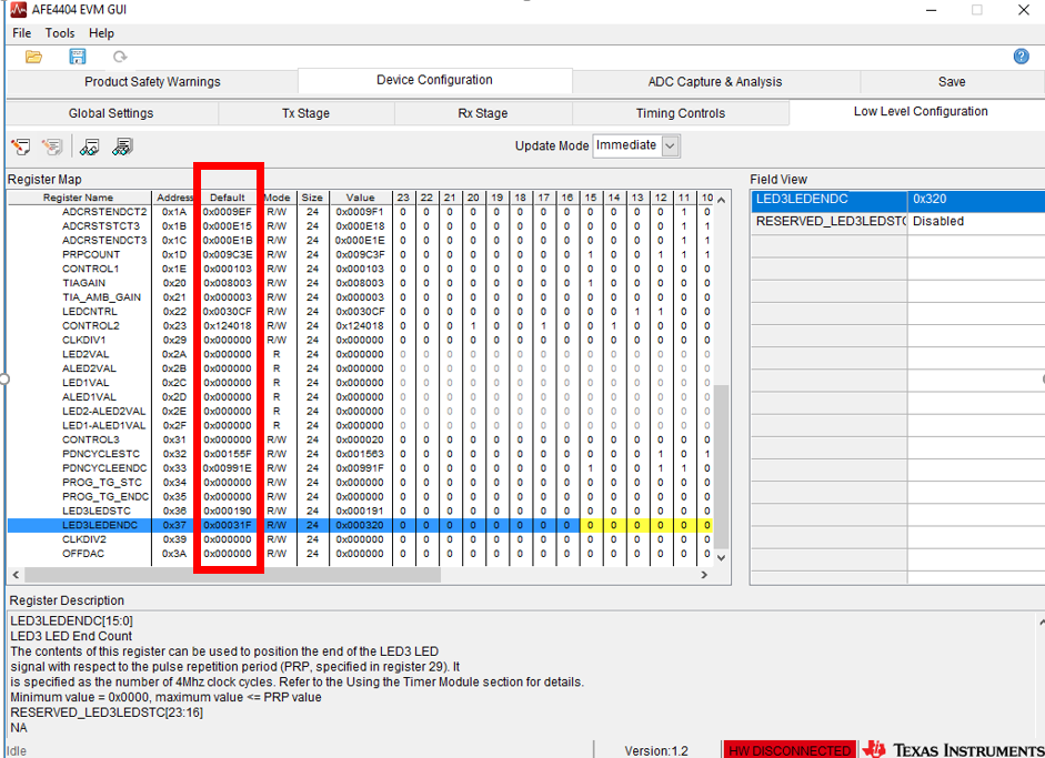
    I tried with the default register as shown below:


    Here are the settings of the registers:

      AFE4404_Disable_Read();
      AFE4404_Reg_Write(1,  0x000050);      //AFE_LED2STC
      AFE4404_Reg_Write(2,  0x00018F);      //AFE_LED2ENDC
      AFE4404_Reg_Write(3,  0x000320);      //AFE_LED1LEDSTC
      AFE4404_Reg_Write(4,  0x0004AF);      //AFE_LED1LEDENDC
      AFE4404_Reg_Write(5,  0x0001E0);      //AFE_ALED2STC
      AFE4404_Reg_Write(6,  0x00031F);      //AFE_ALED2ENDC
      AFE4404_Reg_Write(7,  0x000370);      //AFE_LED1STC
      AFE4404_Reg_Write(8,  0x0004AF);      //AFE_LED1ENDC
      AFE4404_Reg_Write(9,  0x000000);      //AFE_LED2LEDSTC
      AFE4404_Reg_Write(10, 0x00018F);      //AFE_LED2LEDENDC
      AFE4404_Reg_Write(11, 0x0004FF);      //AFE_ALED1STC
      AFE4404_Reg_Write(12, 0x00063E);      //AFE_ALED1ENDC
      AFE4404_Reg_Write(13, 0x000198);      //AFE_LED2CONVST
      AFE4404_Reg_Write(14, 0x0005BB);      //AFE_LED2CONVEND
      AFE4404_Reg_Write(15, 0x0005C4);      //AFE_ALED2CONVST
      AFE4404_Reg_Write(16, 0x0009E7);      //AFE_ALED2CONVEND
      AFE4404_Reg_Write(17, 0x0009F0);      //AFE_LED1CONVST
      AFE4404_Reg_Write(18, 0x000E13);      //AFE_LED1CONVEND
      AFE4404_Reg_Write(19, 0x000E1C);      //AFE_ALED1CONVST
      AFE4404_Reg_Write(20, 0x00123F);      //AFE_ALED1CONVEND
      AFE4404_Reg_Write(21, 0x000191);      //AFE_ADCRSTSTCT0
      AFE4404_Reg_Write(22, 0x000197);      //AFE_ADCRSTENDCT0
      AFE4404_Reg_Write(23, 0x0005BD);      //AFE_ADCRSTSTCT1
      AFE4404_Reg_Write(24, 0x0005C3);      //AFE_ADCRSTENDCT1
      AFE4404_Reg_Write(25, 0x0009E9);      //AFE_ADCRSTSTCT2
      AFE4404_Reg_Write(26, 0x0009EF);      //AFE_ADCRSTENDCT2
      AFE4404_Reg_Write(27, 0x000E15);      //AFE_ADCRSTSTCT3
      AFE4404_Reg_Write(28, 0x000E1B);      //AFE_ADCRSTENDCT3
      AFE4404_Reg_Write(29, 0x009C3E);      //AFE_PRPCOUNT
      AFE4404_Reg_Write(30, 0x000103);      //AFE_CONTROL1 TimerEN = 1; NUMAV = 3
      AFE4404_Reg_Write(32, 0x008003);      //AFE_TIA_SEP_GAIN (LED2) ENSEPGAIN = 1; LED2/LED3 gain = 50K
      AFE4404_Reg_Write(33, 0x000003);      //AFE_TIA_GAIN (LED1) LED1/LED1AMB gain = 50K
      AFE4404_Reg_Write(34, 0x0030CF);      //LED3 - 3.125mA; LED2 - 3.125mA; LED1 - 12.5mA
      AFE4404_Reg_Write(35, 0x124018);      //DYN1, LEDCurr, DYN2, Ext CLK, DYN3, DYN4 //0x000200); - 0x200 Osc mode //AFE_CONTROL2
      AFE4404_Reg_Write(41,  0x000000);      //AFE_CLKDIV1
      AFE4404_Reg_Write(49, 0x000000);      //ENABLE_INPUT_SHORT
      AFE4404_Reg_Write(50, 0x00155F);      //AFE_DPD1STC
      AFE4404_Reg_Write(51, 0x00991E);      //AFE_DPD1ENDC
      AFE4404_Reg_Write(52,  0x000000);      //AFE_PROG_TG_STC
      AFE4404_Reg_Write(53,  0x000000);      //AFE_PROG_TG_ENDC
      AFE4404_Reg_Write(54, 0x000190);      //AFE_LED3LEDSTC
      AFE4404_Reg_Write(55, 0x00031F);      //AFE_LED3LEDENDC
      AFE4404_Reg_Write(57, 0x000000);      //AFE_CLKDIV_PRF
      AFE4404_Reg_Write(58, 0x000000);      //AFE_DAC_SETTING_REG
      AFE4404_Enable_Read();

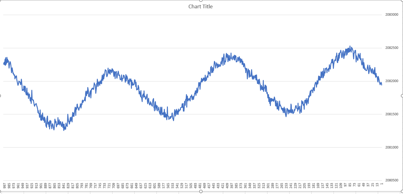
    But the waveform that I see after 10 seconds from the 0x2F register look like:

    (It looks like there should have been at least double pulses in that amount of time )

    What do you think is the problem?

    Thanks in advance,

    Oshrit

  • Hi Oshrit,

    You might be picking noise from AC mains.
    Try running your test from battery powered device.

    Regards,
    Prabin
  • Hi Prabin,

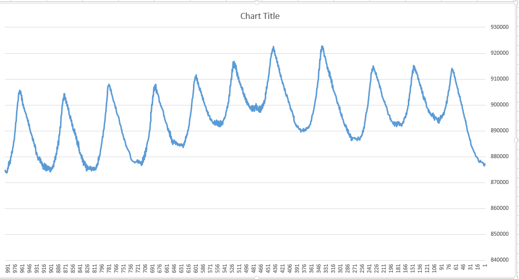
    Thanks for your help. It seems like it's working ok now.

    You can see below.

    Best Regards,

    Oshrit

  • Hi Oshrit,

    Glad to hear that.

    Regards,
    Prabin
  • Hi Prabin,

    Thanks for your help in the past!

    The graph that I attached in the past, was from the green LED. 

    Can I get this graph also from the Red LED?

    Thanks,

    Oshrit 

  • Hi Oshrit,

    From AFE point of view it doesn't matter what color LED is used.
    You will get the PPG waveform using RED LED but the signal strength might not be same as compared to the green one.

    Regards,
    Prabin
  • Hi Prabin,

    Thanks for your quick answer.
    When I measure with the RED LED (and my finger is attached to the LEDs) I get the same value the whole time : 2096921.
    Does this mean I am not configuring the registers right?
    If so, witch one and how?

    Thanks again,
    Oshrit
  • Hi Oshrit,

    ADC code of 2096921 means saturation of the ADC. So you can try following things.
    1) Cancel the DC using offset DAC
    2) Lower the LED current
    3) Lower the TIA Gain

    Regards,
    Prabin
  • Hi Prabin,

    Firstly, thanks for your reply.

    I had a question regarding the first point you wrote:

    Cancel the DC using offset DAC - do you mean I need to reset register: ox3A?

    Thanks in advance,

    Oshrit

  • Hi Oshrit,

    Yes, you can program the offset cancellation DAC with 0x3A register to cancel the ambient.
    You don't have to reset 0x3A.
    Set the polarity bit to 1 to subtract the ambient at the TIA input. The level of the DAC's current is controlled by "I_OFFDAC_LEDn" field, please refer to Table 74 of the datasheet for mapping of this field with the current.

    Regards,
    Prabin