This thread has been locked.

If you have a related question, please click the "Ask a related question" button in the top right corner. The newly created question will be automatically linked to this question.

PGA970EVM questions

Other Parts Discussed in Thread: USB2ANY, PGA970EVM, PGA970

Hi team,

The customer is using PGA970EVM. The configuration is the same as Table 1. Default PGA970EVM Jumper Configuration of the user's guide.

His PC system is XP system. There are two cases are as below:

Case 1. The PGA970EVM is not connected the external power. The customer uses the USB2ANY to connect the  PGA970EVM.

And the PGA970EVM can be communicated with the USB2ANY. The LED of the USB2ANY board begins to flash and then it is always on. 

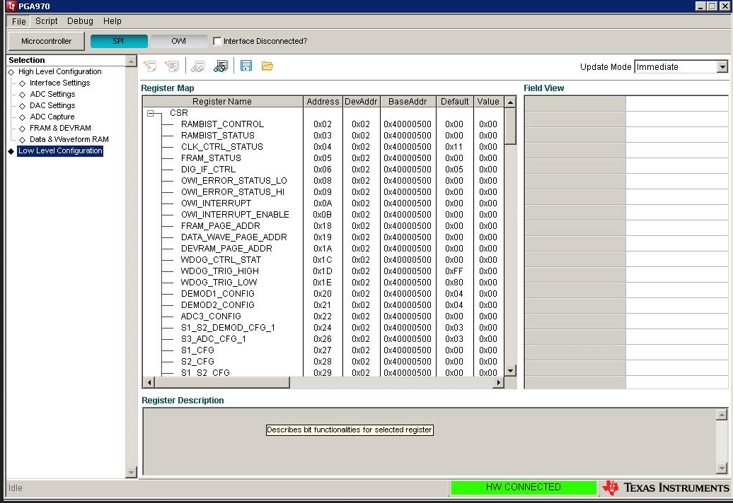
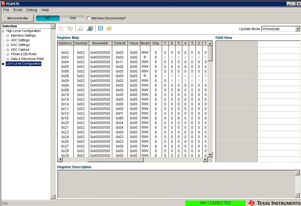
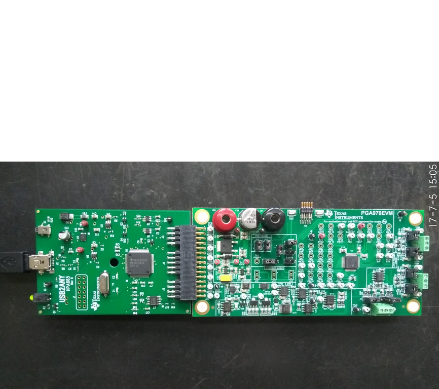
But when the customer clicks the "Read all"t button, the register data of the GUI is all 0. Please check the attach for the connecting of the USB2ANY and

the PGA970EVM, and the GUI register data.  

Case 2. The PGA970EVM is  connected the external power. The external power is DC12V. The external power is connected J20 and J21. 

Then the customer test the voltages for the PGA970EVM. Test result: TP21 is 12V. TP6(AVDD)is 2.85V. TP9(DVDD)is 1.86V.

The USB2ANY is connected the PGA970EVM. The LED of the USB2ANY board is always on.

But the PGA970EVM cannot be communicated with the  USB2ANY.

Q1: For the case 1, the PGA970EVM is not connected the external power. Should the external power be needed when the customer used the PGA970EVM?

If the external power can be not needed, would you explain why the GUI register data is all 0 for the case 1?

Q2: For the case 2, TP6(AVDD)is 2.85V. TP9(DVDD)is 1.86V. The datasheet shows the AVDD is 3V and the DVDD is 1.8V. 

Are  2.85V for AVDD and 1.86V for DVDD correct? 

Is there any reason that why PGA970EVM cannot be communicated with the  USB2ANY?

Best Wishes,
Mickey Zhang
Asia Customer Support Center
Texas Instruments

  • Hi Mickey! I was digging through the forums for an answer to a different question, but I believe I can answer yours in passing.
    ____________________________________________________________________________________________________________________
    Q1: For the case 1, the PGA970EVM is not connected the external power. Should the external power be needed when the customer used the PGA970EVM?

    If the external power can be not needed, would you explain why the GUI register data is all 0 for the case 1?
    ____________________________________________________________________________________________________________________
    Mickey, you need external power. The USB2ANY will not give any indications that it cannot talk to the PGA970_EVM, and will return 0x00 for all reads. Without power, the processor cannot talk over the SPI interface, and the USB2ANY does not supply the PGA970 with power. To my knowledge, there is no other way to power the PGA970_EVM other than using the banana jacks provided.
    ____________________________________________________________________________________________________________________
    Q2: For the case 2, TP6(AVDD)is 2.85V. TP9(DVDD)is 1.86V. The datasheet shows the AVDD is 3V and the DVDD is 1.8V.

    Are 2.85V for AVDD and 1.86V for DVDD correct?
    ____________________________________________________________________________________________________________________
    Nominally, the voltages should be 3V for AVDD and 1.85V (page 6 of datasheet). The datasheet does not indicate a range of acceptable values, just the expected nominal voltage. In my experience, 2.85V would be a little low for a digital logic level, and 1.86V would be acceptable for 1.85V. Even though 2.85V is a little low, I wouldn't expect unusual behavior to result from it.

    -Will
  • Hi Will,

    Thanks for your help. But there is no banana jacks interface on the PGAP70EVM. Do you know this ? The customer needs to connect the external power to J20 and J21.

  • Mickey Zhang said:

    Hi Will,

    Thanks for your help. But there is no banana jacks interface on the PGAP70EVM. Do you know this ? The customer needs to connect the external power to J20 and J21.

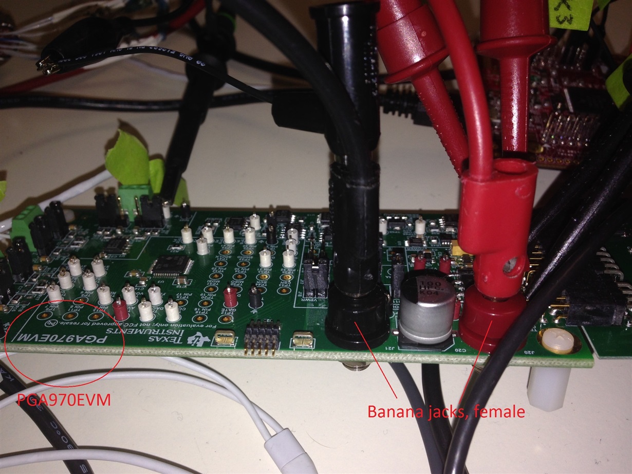
    Hi Mickey! You show them up in your picture of the board. J20 and J21 are the red and black, female banana jack inputs. If you're referring to the fact male plugs with a cable are not supplied, then I believe you are correct. You will have to order to purchase them separately.
    If the other customer has removed the nuts on the underside of the female sockets, then the female banana jacks can be removed. You could also attach terminal lugs to the underside of the banana jack sockets using a 3/8" nut. Since you say the part isn't there, I'm wondering if the other customer unscrewed the part or whether some boards were shipped without them. That I dont know, any you'd have to check with the other customer. Replacement part is: SPC15354 -> black one, and SPC15363 -> red one. Newark appears to stock both.

    This is my board, currently, with my external connections to J20 and J21. You can see the threading on the female banana jack socket sticking out underneath, where you could use terminal lugs to connect. I think the resolution is high enough that you should be able to make out the J20 and J21 silk screen marks, and the 

  • Hi Will,

    OK. Thanks for your help. When my customer connects the external power DC12V to J20 and J21, the GUI software will automatically jump to Interface Disconnected mode. Then he cannot connect the GUI software to the Interface connected mode.

    Would you have met this situation?
  • Mickey

    Case 1 ,so do I;
    Case 2 ,i am ok, whether if external power connect, HW CONNECT is OK. My computer is windows 7.

    Wang Jie
  • Because the software is likely identical between our two versions, I am guessing this is either a hardware or firmware failure in either the PGA970EVM or USB2ANY boards. Mostly because I cant duplicate that result by powering any board in particular order.

    So let me try to help you troubleshoot:
    1. Are both the PGA970EVM and USB2ANY boards facing upwards? It's possible to flip the USB2ANY board over and plug it into the PGA970EVM upside down. A short may disable connecting to the USB2ANY board. I am defining "upwards" as you can read the silkscreen on the PGA970EVM that says "PGA970EVM", and likewise you can see "USB2ANY" on the USB2ANY board.
    2. You can try re-uploading the firmware to the USB2ANY board. I recommend separating your boards before doing so, only because you may have a board fault on one of the boards that prevents the firmware update from working. To update the firmware, start the GUI, then disconnect the physical USB cable from my computer, which causes the GUI to enter interface disconnected mode. Then, while pressing in button S1 in the corner of the USB2ANY board connect the USB cable back to the computer. Release the button after making the connection. The GUI should then prompt you to load the firmware onto the board. Try to see if the board works after the firmware update.
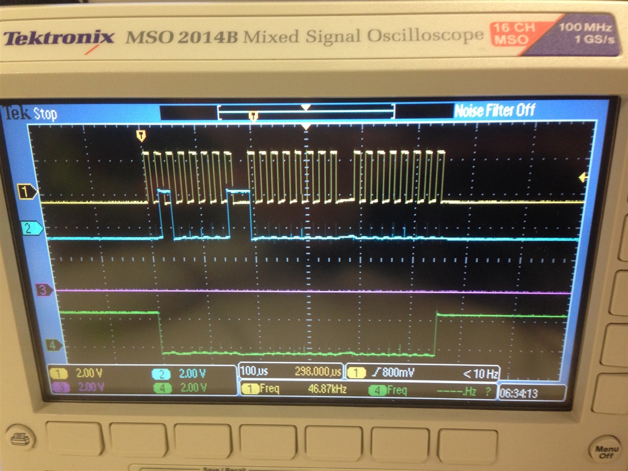
    3. With power not applied to the PGA970EVM but both boards connected, send SPI commands from the USB2ANY over the SPI interface while watching the CSN (chip select), SIMO (Slave in, Master out), SOMI (Slave out, Master in), and SCLK (SPI clock) pins with an oscilloscope. Below is a read command of some register -> select any register in the low level configuration page of the GUI and press the read button located above the register list. You should see something like below, where yellow is the clock, green is the chip select, and cyan is SIMO. Magenta is SOMI, which should not give you a response, as power is not applied to the PGA970EVM.

    4. Is the power supply you are providing the 12V over an isolated output? Or a ground-referenced power supply?

    Check these things, and let me know the response from your unit.