This thread has been locked.

If you have a related question, please click the "Ask a related question" button in the top right corner. The newly created question will be automatically linked to this question.

TMP112 Interfacing help

Other Parts Discussed in Thread: TMP112, TMP102, CC2650, TMP007

Hi everyone,

I am trying to use dsPIC33F to interface with my TMP112 temperature sensor. However, I am running into some weird issue. It looks like I was able to write to the slave TMP112 and receive the Acknowledge(ACK). However, I am not able to receive the data sent from the TMP112 device. Any thoughts on why?

I am running at Fscl = 100kHz.

below is the main temperature read function.

double I2C_Read_Temperature(){

unsigned char I2C1_TX_BUF[1];
I2C1_TX_BUF[0]=Temperature_Register;

I2C1_Write(1,I2C1_TX_BUF); //byte length one.
//I2C1_Write is a complete write function that includes Start bit,
//data transmit, and Stop bit.

/*initialize RX Buffer*/
I2C1_RX_BUF[0]=0;
I2C1_RX_BUF[1]=0;

I2C1_Read(2); //read in data of 2 byte
//I2C1_Read is a complete read function that first write Read to the slave
// and then start reading data.
unsigned char T_H = I2C1_RX_BUF[0];
unsigned char T_L = I2C1_RX_BUF[1];

double temperatureResult = Decimal_Convert(T_H,T_L);

return temperatureResult;

}

thank you for your help!

Chih-Wei 

  • Hello Chih-Wei,

    It's almost impossible to exactly pin point the bug when you are trying to build an interface communication protocol from scratch. There could be one or multiple issues with this and let me help you corner the issue. Following are the things I would like you to take a closer look at...

    1. In your I2C write byte code:  I2C1_Write(1,I2C1_TX_BUF); //byte length one. 
                                                         //I2C1_Write is a complete write function that includes Start bit, 
                                                         //data transmit, and Stop bit.

      Since I2C1_Write function is 1 byte. This function cannot include the "Stop bit" Because once you send STOP you need to restart the communication from scratch by sending a START bit. 

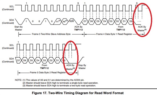
    2. Your I2C1_Read function is a 2 Byte read function. Does it include the Acknowledge (ACK- as shown in the picture) at the end of 1st and 2nd Byte read? Please refer to the following picture. You may also get more information on I2C read working from Page 15 of the data sheet.

    3. I don't see that you are sending a  STOP bit from the after to perform the I2C1_Read function. Is it included in the end of  I2C1_Read functipn?

    4. Last but not the least, how are you monitoring the SCL and SDA lines? Using an oscilloscope will help you debug  and compare with the protocol pictures in the datasheet. If you are trying to debug the communication just by using your C code it might take longer to figure out the issue. (Just a thought)

    Hope you corner the issue and start talking to TMP112 soon!

    Best Regards,

    Abhi Muppiri

    Applications Engineer

    AIP- Sensing Products


  • Hello Abhi,

    Thank you for your quick response.

    1.

    You are absolutely right, I did find out about that additional STOP bit, and I was suspecting that might come from the error from the datasheet. Perhaps you guys can take a loop and update the datasheet for the timing diagram. The datasheet for TMP112 did not mention this additional STOP bit in the description(Slave Transmitter Mode section). 

    2. ACK is included in the I2C1_Read.

    3. Yes, the STOP is generated at the end of I2C_Readl

    4. This is also one of the difficulties, and I have been unsuccessful in seeing the timing diagram shown above. I tried to scope it, and all I see is the bus sometimes being pulled up and then down. Is there some setting/configuration of the oscilloscope that I didn't do correctly perhaps?

    Thank you very much for your help. If it helps you to more understand my code, I based my code on this website:

    ftp://apollo.ssl.berkeley.edu/pub/cinema/06.%20Spacecraft/4.%20Electrical%20Power%20System/EPS%20Software%20-%20KHU/EPS_Test_v0.09/Src/I2C.c.txt

    I have only made small changes, but nothing big that changes the algorithm. The above I2C1_Read_Temperature function is done simply by using the I2C1_Read and I2C1_Write. 

    I do have a few question, and hopefully you can clarify for me.

    1. What is the difference between I2C and Two-Wire Interface? Many online resources suggest they are almost inter-compatible.

    2. One of my co-worker mentioned to me that when I scope the SCL bus, I should see the clock constantly running ALL THE TIME, and that is done by feeding a timer clock into the SCL bus. However, from my understanding of I2C/Two-Wire, I thought the SCL is only clocking when there is a START, and nothing should happen after the STOP bit.  Could you clarify this issue for me? Thank you!

    Lastly, I will try to remove that STOP bit and try again today.

    Thank you very much for your help and support!

    Chih-Wei Tang

  • Hello Chih-Wei,

    Glad I could help you out. The data sheet is correct in this case because if you see in the diagram that you attached after the STOP bit there is a Start/ Repeat-Start  immediately after that.

    To clarify your questions:

    1. What is the difference between I2C and Two-Wire Interface? Many online resources suggest they are almost inter-compatible.

    They are mostly similar and often inter-compatible

    2. One of my co-worker mentioned to me that when I scope the SCL bus, I should see the clock constantly running ALL THE TIME, and that is done by feeding a timer clock into the SCL bus. However, from my understanding of I2C/Two-Wire, I thought the SCL is only clocking when there is a START, and nothing should happen after the STOP bit.  Could you clarify this issue for me? Thank you!

    It doesn't really matter if SCL clocks all the time or not as long as the SDA line is High when there no communication. It depends on the Master device, and depends if there are multiple I2C Slave devices connected to the same bus. Obviously you save power if there in no activity on the SCL line when there is no communication through SDA line.


    Best Regards,

     Abhi Muppiri

    Applications Engineer

    AIP- Sensing Products

    Texas Instruments 


  • Hi Abhi,

    thanks for your email. Would you mind explaining to me why I didn't see much happening on the oscilloscope? If I can get it work, that will definitely help dramatically!

    Thank you

    Chih-Wei Tang

  • Hello Chih-Wei,

    I really tough for me to direct you on this aspect because it varies from Scope to scope. I can give you some pointers that would probably help you in general though...

    1.Make sure your volatage dispay is set to the right value.

    2. Make sure you check and set the trigger voltage level to the right value. 

    3. Make sure your trigger  point is displayed, preferably at the center of your scope screen

    4. Do a single trigger and then initialize your communication to see the first activity on SCL or SDA lines

    Best Regards, 

    Abhi Muppiri

    Applications Engineer

    AIP- Sensing Products

    Texas Instruments

  • Hello Chih-Wei,

    If you are still facing issues with your Serial interface communication, I have a suggestion for you:

    Some of our temp sensors have an evaluation module(EVM) that readily available for measurements. Once you get an EVM all you need to do is just plug and play to find out the temperature, read/write to registers etc.  Just probe the SCL and SDA lines of the EVM so you can observe their behavior on the scope. Once you have this, all you need to do is to try and mimic this on to your C code.

    TMP102 follows similar 2 wire communication as TMP112 and here is the link to its EVM:

    http://www.ti.com/tool/tmp102evm

    Best Regards,

    Abhi Muppiri

    Applications Engineer

    AIP- Sensing Products

    Texas Instruments

  • Hi Abhi,

    Thanks for your email. I am still in the process of getting it to work. Right now, it seems that I am getting the ACK from the slave device when I write to READ TEMPERATURE. However, I am not getting anything from the TMP112 in my buffer. Things are somewhat stuck now. If you have any direction that can provide me to think about, I would highly appreciate it!

    Thank you

    Chih-Wei Tang

  • Hello Chih-Wei,

    Its good to know that you are making progress since you are getting an ACK.

    When you say "I write to READ TEMPERATURE" - I get the feeling that you are performing a write operation which means I2C slave Address followed by Write bit('0') followed by TMP112 ACK. Please make sure you sure you are actually performing a Read operation instead. Which is I2C Slave address followed by Read bit ('1') followed by TMP112 Slave ACK.

    It would be easy for me to help you if you can send me a snapshot of your activity on SCL and SDA lines. Also, please refer to the diagram from the data sheet that I attached  and please make sure you are replicating it cycle by cycle.

    Good Luck!


    Best Regards,

    Abhi Muppiri

    Applications Engineer

    AIP- Sensing Products

    Texas Instruments 

  • hi abhishek

    I am using a tmp112 sensor instead of tmp007 sensor in cc2650 sensor tag and I have to make it communicate it via i2c . I was given a sample code . I am using IAR for changing firmware. I don't need Linux . So what are the include files that must be added. How do I proceed if I have a reference code for tmp007 . ´what should be changed

    #include <linux/module.h>
    #include <linux/init.h>
    #include <linux/slab.h>
    #include <linux/i2c.h>
    #include <linux/hwmon.h>
    #include <linux/hwmon-sysfs.h>
    #include <linux/err.h>
    #include <linux/mutex.h>
    #include <linux/device.h>
    #include <linux/jiffies.h>
    #include <linux/thermal.h>
    #include <linux/of.h>

    #define DRIVER_NAME "tmp112"

    #define TMP102_TEMP_REG 0x00
    #define TMP102_CONF_REG 0x01

    /* note: these bit definitions are byte swapped */
    #define TMP102_CONF_SD 0x0100
    #define TMP102_CONF_TM 0x0200
    #define TMP102_CONF_POL 0x0400
    #define TMP102_CONF_F0 0x0800
    #define TMP102_CONF_F1 0x1000
    #define TMP102_CONF_R0 0x2000
    #define TMP102_CONF_R1 0x4000
    #define TMP102_CONF_OS 0x8000
    #define TMP102_CONF_EM 0x0010
    #define TMP102_CONF_AL 0x0020
    #define TMP102_CONF_CR0 0x0040
    #define TMP102_CONF_CR1 0x0080
    #define TMP102_TLOW_REG 0x02
    #define TMP102_THIGH_REG 0x03

    struct tmp102 {
    struct i2c_client *client;
    struct device *hwmon_dev;
    struct thermal_zone_device *tz;
    struct mutex lock;
    u16 config_orig;
    unsigned long last_update;
    int temp[3];
    };

    /* convert left adjusted 13-bit TMP102 register value to milliCelsius */
    static inline int tmp102_reg_to_mC(s16 val)
    {
    return ((val & ~0x01) * 1000) / 128;
    }

    /* convert milliCelsius to left adjusted 13-bit TMP102 register value */
    static inline u16 tmp102_mC_to_reg(int val)
    {
    return (val * 128) / 1000;
    }

    static const u8 tmp102_reg[] = {
    TMP102_TEMP_REG,
    TMP102_TLOW_REG,
    TMP102_THIGH_REG,
    };

    static struct tmp102 *tmp102_update_device(struct device *dev)
    {
    struct tmp102 *tmp102 = dev_get_drvdata(dev);
    struct i2c_client *client = tmp102->client;

    mutex_lock(&tmp102->lock);
    if (time_after(jiffies, tmp102->last_update + HZ / 3)) {
    int i;
    for (i = 0; i < ARRAY_SIZE(tmp102->temp); ++i) {
    int status = i2c_smbus_read_word_swapped(client,
    tmp102_reg[i]);
    if (status > -1)
    tmp102->temp[i] = tmp102_reg_to_mC(status);
    }
    tmp102->last_update = jiffies;
    }
    mutex_unlock(&tmp102->lock);
    return tmp102;
    }

    static int tmp102_read_temp(void *dev, long *temp)
    {
    struct tmp102 *tmp102 = tmp102_update_device(dev);

    *temp = tmp102->temp[0];

    return 0;
    }

    static ssize_t tmp102_show_temp(struct device *dev,
    struct device_attribute *attr,
    char *buf)
    {
    struct sensor_device_attribute *sda = to_sensor_dev_attr(attr);
    struct tmp102 *tmp102 = tmp102_update_device(dev);

    return sprintf(buf, "%d\n", tmp102->temp[sda->index]);
    }

    static ssize_t tmp102_set_temp(struct device *dev,
    struct device_attribute *attr,
    const char *buf, size_t count)
    {
    struct sensor_device_attribute *sda = to_sensor_dev_attr(attr);
    struct tmp102 *tmp102 = dev_get_drvdata(dev);
    struct i2c_client *client = tmp102->client;
    long val;
    int status;

    if (kstrtol(buf, 10, &val) < 0)
    return -EINVAL;
    val = clamp_val(val, -256000, 255000);

    mutex_lock(&tmp102->lock);
    tmp102->temp[sda->index] = val;
    status = i2c_smbus_write_word_swapped(client, tmp102_reg[sda->index],
    tmp102_mC_to_reg(val));
    mutex_unlock(&tmp102->lock);
    return status ? : count;
    }

    static SENSOR_DEVICE_ATTR(temp1_input, S_IRUGO, tmp102_show_temp, NULL , 0);

    static SENSOR_DEVICE_ATTR(temp1_max_hyst, S_IWUSR | S_IRUGO, tmp102_show_temp,
    tmp102_set_temp, 1);

    static SENSOR_DEVICE_ATTR(temp1_max, S_IWUSR | S_IRUGO, tmp102_show_temp,
    tmp102_set_temp, 2);

    static struct attribute *tmp102_attrs[] = {
    &sensor_dev_attr_temp1_input.dev_attr.attr,
    &sensor_dev_attr_temp1_max_hyst.dev_attr.attr,
    &sensor_dev_attr_temp1_max.dev_attr.attr,
    NULL
    };
    ATTRIBUTE_GROUPS(tmp102);

    #define TMP102_CONFIG (TMP102_CONF_TM | TMP102_CONF_EM | TMP102_CONF_CR1)
    #define TMP102_CONFIG_RD_ONLY (TMP102_CONF_R0 | TMP102_CONF_R1 | TMP102_CONF_AL)

    static int tmp102_probe(struct i2c_client *client,
    const struct i2c_device_id *id)
    {
    struct device *dev = &client->dev;
    struct device *hwmon_dev;
    struct tmp102 *tmp102;
    int status;

    if (!i2c_check_functionality(client->adapter,
    I2C_FUNC_SMBUS_WORD_DATA)) {
    dev_err(dev,
    "adapter doesn't support SMBus word transactions\n");
    return -ENODEV;
    }

    tmp102 = devm_kzalloc(dev, sizeof(*tmp102), GFP_KERNEL);
    if (!tmp102)
    return -ENOMEM;

    i2c_set_clientdata(client, tmp102);
    tmp102->client = client;

    status = i2c_smbus_read_word_swapped(client, TMP102_CONF_REG);
    if (status < 0) {
    dev_err(dev, "error reading config register\n");
    return status;
    }
    tmp102->config_orig = status;
    status = i2c_smbus_write_word_swapped(client, TMP102_CONF_REG,
    TMP102_CONFIG);
    if (status < 0) {
    dev_err(dev, "error writing config register\n");
    goto fail_restore_config;
    }
    status = i2c_smbus_read_word_swapped(client, TMP102_CONF_REG);
    if (status < 0) {
    dev_err(dev, "error reading config register\n");
    goto fail_restore_config;
    }
    status &= ~TMP102_CONFIG_RD_ONLY;
    if (status != TMP102_CONFIG) {
    dev_err(dev, "config settings did not stick\n");
    status = -ENODEV;
    goto fail_restore_config;
    }
    tmp102->last_update = jiffies - HZ;
    mutex_init(&tmp102->lock);

    hwmon_dev = hwmon_device_register_with_groups(dev, client->name,
    tmp102, tmp102_groups);
    if (IS_ERR(hwmon_dev)) {
    dev_dbg(dev, "unable to register hwmon device\n");
    status = PTR_ERR(hwmon_dev);
    goto fail_restore_config;
    }
    tmp102->hwmon_dev = hwmon_dev;
    tmp102->tz = thermal_zone_of_sensor_register(hwmon_dev, 0, hwmon_dev,
    tmp102_read_temp, NULL);
    if (IS_ERR(tmp102->tz))
    tmp102->tz = NULL;

    dev_info(dev, "initialized\n");

    return 0;

    fail_restore_config:
    i2c_smbus_write_word_swapped(client, TMP102_CONF_REG,
    tmp102->config_orig);
    return status;
    }

    static int tmp102_remove(struct i2c_client *client)
    {
    struct tmp102 *tmp102 = i2c_get_clientdata(client);

    thermal_zone_of_sensor_unregister(tmp102->hwmon_dev, tmp102->tz);
    hwmon_device_unregister(tmp102->hwmon_dev);

    /* Stop monitoring if device was stopped originally */
    if (tmp102->config_orig & TMP102_CONF_SD) {
    int config;

    config = i2c_smbus_read_word_swapped(client, TMP102_CONF_REG);
    if (config >= 0)
    i2c_smbus_write_word_swapped(client, TMP102_CONF_REG,
    config | TMP102_CONF_SD);
    }

    return 0;
    }

    #ifdef CONFIG_PM
    static int tmp102_suspend(struct device *dev)
    {
    struct i2c_client *client = to_i2c_client(dev);
    int config;

    config = i2c_smbus_read_word_swapped(client, TMP102_CONF_REG);
    if (config < 0)
    return config;

    config |= TMP102_CONF_SD;
    return i2c_smbus_write_word_swapped(client, TMP102_CONF_REG, config);
    }

    static int tmp102_resume(struct device *dev)
    {
    struct i2c_client *client = to_i2c_client(dev);
    int config;

    config = i2c_smbus_read_word_swapped(client, TMP102_CONF_REG);
    if (config < 0)
    return config;

    config &= ~TMP102_CONF_SD;
    return i2c_smbus_write_word_swapped(client, TMP102_CONF_REG, config);
    }

    static const struct dev_pm_ops tmp102_dev_pm_ops = {
    .suspend = tmp102_suspend,
    .resume = tmp102_resume,
    };

    #define TMP102_DEV_PM_OPS (&tmp102_dev_pm_ops)
    #else
    #define TMP102_DEV_PM_OPS NULL
    #endif /* CONFIG_PM */

    static const struct i2c_device_id tmp102_id[] = {
    { "tmp102", 0 },
    { }
    };
    MODULE_DEVICE_TABLE(i2c, tmp102_id);

    static struct i2c_driver tmp102_driver = {
    .driver.name = DRIVER_NAME,
    .driver.pm = TMP102_DEV_PM_OPS,
    .probe = tmp102_probe,
    .remove = tmp102_remove,
    .id_table = tmp102_id,
    };

    module_i2c_driver(tmp102_driver);
  • why isn't the slave address defined here. should the slave address be defined for the i2c interface
  • Hi

    I replied to you on your other post.

    e2e.ti.com/.../1631237
  • could somebody give me the code for tmp112 communication with cc2650 via i2c. I am finding it really difficult to replace tmp007 with tmp112 and communicate via i2c
  • Hi Shivaraman,

    This is a working code for the TMP112 with the MSP430. Hope you can use this as reference. 

    Regards,

    TMP112v1.zip