This thread has been locked.

If you have a related question, please click the "Ask a related question" button in the top right corner. The newly created question will be automatically linked to this question.

TMP006 sensor data read/write problem

Other Parts Discussed in Thread: TMP006, TMP007

Hi,

        I am working with TMP006 sensor and PIC 16F877A . I had already interfaced the sensor with PIC using I2C. The problem is when I had tried to send the slave address initially, the slave does not responds ie  I don't get any acknowledgement from the slave.So it stays in the loop. Here I had given TMP006 address as 0x40(only using one sensor). So I don't not connect ADR0,ADR1and DRDY pins. Is this a problem for not getting the acknowledgement from slave?. I had attached the code along this thread. Can somebody suggest solution for this..

Regards,

Nithn

void write16(unsigned int addr, unsigned int reg, unsigned long data)
{
	I2C_Start();										// Start i2c communication
        //
        //!!!!here is the problem, the slave dosen't acknowledges and stay's in the loop
        //
	while((I2C_Write_Byte(addr + 0) == 0));
	I2C_Write_Byte(reg);				                                 // Write Address byte
	I2C_Write_Byte(data >> 8);							// Write data byte
	I2C_Write_Byte((unsigned char)data);
	I2C_Stop();											// Stop i2c communication
}

  • Nithn,

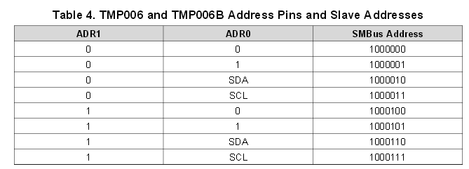
    Per section "8.3.8.1 Serial Bus Address" in the TMP006 data sheet, the A0 and A1 pins of the device must be hooked to power, ground, SDA or SCL. Table 4 shows the resultant addresses for communication.

    Leaving DRDY floating is ok since it is an output and only necessary for interrupt-driven systems.
  • Hi,

          I had found that the maximum supply voltage for TMP006 can be upto 7V(refer the attachment below from datasheet). But the online content for TMP006 ie in the description and parametrics section mentioning that the TMP006 maximum supply voltage can only be upto 3.6V. What was the exact maximum supply voltage in which the TMP006 can work normally. Actually I am using PIC 16F877A, so my common supply is 5V and will this voltage be enough for the TMP006 as well?. Just asking for curiosity, can the IR radiations emitting from the TMP006 sensor may be visible on the mobile phone camera?

    TMP.docx

    Regards,

    Nithin

  • Nithin,

      The absolute max supply for both TMP006 and TMP007 is 7V.  But The recommended Max operating Voltage is  5.5V.  I have opperated the part at 5.5V and it works nicely. Regarding you question about IR emission.  TMP006 is a thermal pile based sensor.  It is an IR absorber.  It is not an IR emitter.  Please let us know if there is anything else we can help you with.


    Regards,

    Tommy Santoyo

    TI-Sensng Apps Team

  • Hi,

            As per the previous threads, I had connected the ADR0 and ADR1 to pulled down resistors(Here I am using the slave address as 0x40). But the result is same. I had attached my  schematic diagram for TMP006 module along with this. Can you please verify this

    SCHEMATIC1 _ PAGE1.pdf

    Regards,

    Nithin

  • Instead of using 10k resistors to pull down the A0 and A1 lines to GND, just use 0.0 Ohm resistors.

    Jason Bridgmon
  • Hi,

        After all the modifications done as per the suggestions, still struggling to get the output. I had found that the write operation can't be succeeded as the slave is not responding(I had mentioned about this at the first thread) and stay's in the while loop forever. I had done changes in the hardware part. But the result is same. Is it because of some fault in the hardware or software?. Here is the code.

    void write16(unsigned int addr, unsigned int reg, unsigned long data)
    {
    	I2C_Start();										// Start i2c communication
    	while(I2C_Write_Byte(addr + 0) == 1);             // the problem is here
    	I2C_Write_Byte(reg);				// Write Address byte
    	I2C_Write_Byte(data >> 8);							// Write data byte
    	I2C_Write_Byte((unsigned char)data);
    	I2C_Stop();											// Stop i2c communication
    }
    
    bit I2C_Write_Byte(unsigned char Byte)
    {
    	SSPBUF = Byte;		// Send Byte value
    	while(!SSPIF);		// Wait for it to complete
    	SSPIF = 0;			// Clear the flag bit
    
    	return ACKSTAT;		// Return ACK/NACK from slave
    }
    

    This I2C library has been already used to interface EEPROM chip and works fine as well. Can you suggest any solution for this...

    Regards,

    Nithin.

  • Nithin,

    I don't know what addr is in your code.  Does it follow the table below?


    If you still can't get the part to respond, please start probing your SCL and SDA lines and see what is working and what is not.  Send us screenshots of the working and not-working captures, and we can debug further.  I cannot say if it is software or hardware without knowing what the hardware is doing.