This thread has been locked.

If you have a related question, please click the "Ask a related question" button in the top right corner. The newly created question will be automatically linked to this question.

TMP007 multiple control

Other Parts Discussed in Thread: TMP007, CC2650Hello, I need 3 TMP007 connect to 1 MCU for different location temperature monitoring. I found that ADR1 and ADR0 pin from hardware determines the device address, so maybe I can set 3 different pin configuration and access the corresponding sensor data by sending different slave address. For example, 0x40 for (0,0), 0x44 for (1,0). But when I tried to test with the sensortag code with cc2650, I found that no matter my pin configuration is (0, 0) or (1, 0), the sensor data shows only in address equals to 0x44. I would like to ask did I misunderstand the datasheet or is there more steps to go for the slave address assignment and I2C communication? Thank you. Best regards, Webb
  • Hi Web,


    Your understanding is correct and the TMP007 address pins are provided precisely for this type of situations.


    How are the address pins connected? Are they hard-wired or GPIO controlled? Please note that they need to be stable before communication starts.


    If you continue to have problems, please forward a sketch of the wiring diagram and possibly a photo showing bus waveforms.


    Regards,

    Guang-Apps Sensing Products

  • Thank you very much.

    I've verified my hard-wired connection with stable 3.3V/GND and found the same result that:

    (ADR1, ADR0) = (1, 0) or (0, 0).setting can both get sensor data when SENSOR_I2C_ADDRESS defined in Sensor_tmp007.c is 0x44, while (0,0) cannot get data in 0x40.

    I'll do another PCB soldering tomorrow to see if there is some wiring or layout bug. If the same condition exists, I'll simplify the sensorTag code first to narrow down to only TMP007 communication, and then update the SDA/SCL signal with my sketch. 

    Thank you again.

    Best regards,

    Webb

  • Excuse me. I think I still not get it thoroughly.

    I'm a bit confused to map the A2 A1 A0 to the hard-wired ADR1 and ADR0.

    If I connect (0, 0), then SMBus address 0x40, so (A2, A1, A0) = (0, 0, 0)?

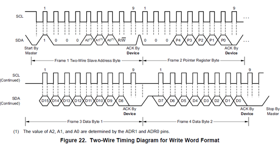
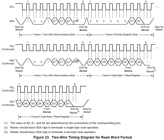
    From Figure 22 it seems reasonable. But how about Figure 23? The slave address bit 4 is 1, so read and write has different slave address?

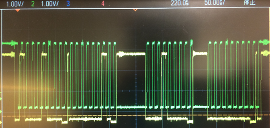
    The following figure is from my software setting 0x44 and hardware setting (0, 0).

    What I think it is to read register 1: Local temperature, and I can see the data keep sending to my phone.

    But it seems to be more like Figure 22 to read data.

    Sorry I haven't successfully do another PCB yet.

    But just from Figure 22, Figure 23, and Table 2 of the datasheet, I'm a bit confused about the slave address concept.

    If any explanation or reference document would be grateful.


    Best regards,

    Webb


  • Hi Webb,


    You are probably reading from a previous version of the data sheet. Please click on here: TMP007, it will bring you to the current data sheet.


    Regards,

    Guang-Apps Sensing Products

  • Hi Guang,

    I got it. Thank you very much!
    So now the problem must be my bad soldering...

    Best regards,
    Webb