This thread has been locked.

If you have a related question, please click the "Ask a related question" button in the top right corner. The newly created question will be automatically linked to this question.

LM57 - not setting outputs when the temp set point is reached.

Other Parts Discussed in Thread: LM57, LM26, LM26LV

I am using an LM57 device to initiate an automatic thermal override shutdown of an induction heater.  Here is the LM57 portion of schematic.
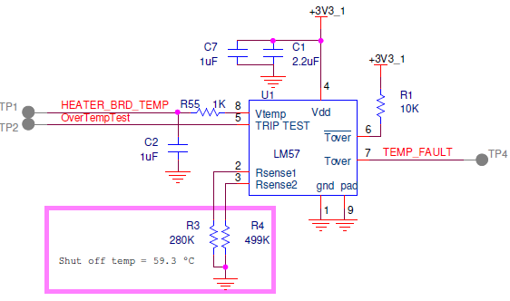
R3: 280K, ±1% ±100ppm/°C  digikey part number: 541-280KHCT-ND  calculated temp drift from 24° to 75° is ≈ 3 ohm

R4: 499K, ±1% ±100ppm/°C  digikey part number: 541-499KHCT-ND  calculated temp drift from 24° to 75° is ≈ 5 ohm

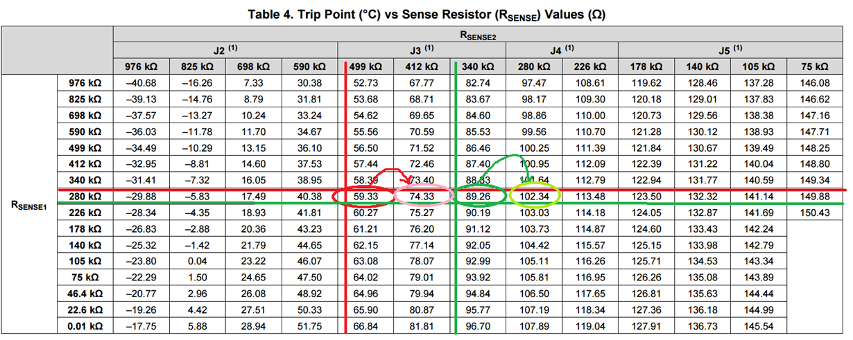
this gives a set point of 59.33°C  and a gain curve of J3.

There is a uController monitoring the Vtemp and the temp accuracy has been verified in a thermal chamber.  The controller is able to run a 'trip test' and the results are as expected, the heater turns off.

The chip is physically located near the induction heater and the temperature is reported properly when the heater is both off and on.

*********************

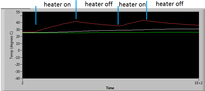
The problem is this: if the heater is on, the LM57 does not activate the Tover outputs until 75°C.  however, if the temp reported is over 60°C and the heater is turned off(manual override) the Tover outputs are immediately activated and remain active until the temp drops T(hyst).

additional information:

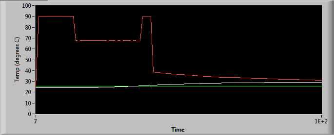
I wanted to test moving the set point out to 90°C so I replaced R4 with 340k ohm and the result was very strange.  When the heater is on the temp reported was incorrect ( ≈ 60°low), but when the heater is off the temp reported is correct.  see below: (red trace)
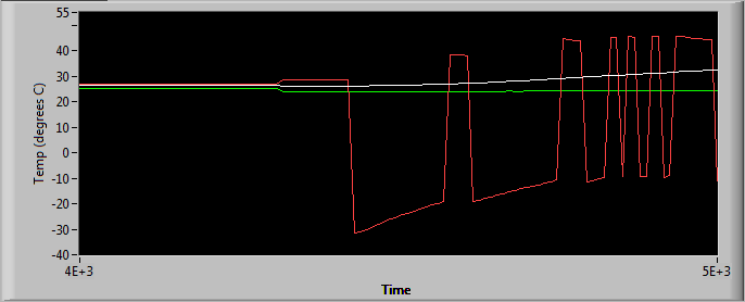
  • something i failed to mention above: when testing the different set point configurations, i was manually turning the heater on and off.
  • Hi David,

    It seems like everything you are doing is correct from the schematic to the performance of the LM57 when the heater is off. Can you tell me more about the heater? The weirdness only comes from when the heater is turned on. Since induction heaters use oscillating electric currents to heat up an object, one hypothesis may be the LM57 is suffering from EMI effects. Is it possible to separate the LM57 and the induction heater, turn on the induction heater and heat up the LM57 to 60C with a heat gun to trigger the outputs?

    -Michael Wong
  • I can test this, but it is not an option for the product.  in any case, the strange temp reporting behavior was only seen with the R3:280k/R4340k configuration. other than that the temp is always reported properly.  the problem is the outputs are not triggering at the proper temperature.

  • i just took a device apart, removed the heater and relocated it 5 inches away from the LM57 (the heater is only about 1.25" in diameter)
    Temp sensor configuration: R3:280k/R4340k Result: the temp sensor reports incorrect temp when heater is on, and correct when heater is off. i tested different orientations of the heater to see if the magnetic field was somehow still interfering. i get the same results in all orientations.
  • Hi David,

    Thanks for conducting this experiment and verifying it is not the magnetic fields affecting the LM57. Two more questions so I can narrow down what can be going wrong: Is the VDD of the LM57 and the induction heater connected together? Does this happen with another LM57 in your setup?

    -Michael Wong
  • The heater and temp sensor are on separate isolated power supplies. and yes, the problem persists across multiple units.
  • After crunching a lot of data I came up with a theory; this morning I tested and verified it.

    The DAC in the LM57 is being affected by heater drive current; even though the heater drive traces are separated from the LM57 by a full ground plane and is placed on the opposite side of the board.  The LM57 is part of a circuit that will shut down the heater if it sees anything over 60°C.

    I verified my theory by disconnecting the T(over) output from the heater shutdown circuit and setting the LM57 to ‘trip test’.   This means that the Temp output will be the DAC voltage, and the T(over) will not shut off the heater.

    I have evaluated two different configurations:

    R3:280k; R4340k

    When the heater is off the temp output of the LM57 is evaluated by software as 90°C.  With the heater on the temp read out is 67°C.  both temps are evaluated with the J3 gain curve.  If the output is evaluated with the J4 gain curve it is actually set to 102°C.

    R3:280; R4:499k

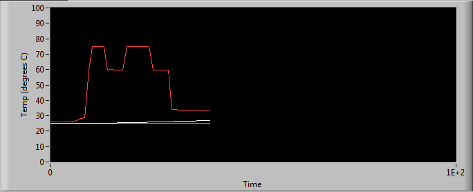
    When the heater is off the temp output of the LM57 is evaluated by software as 60°C.  With the heater on the temp read out is 75°C.  both temps are evaluated with the J3 gain curve. 

    This all makes sense when compared to Table 4 in the LM57 data sheet:

  • Hi David,

    Can you compare the ground level with the heater on and off? I have a feeling something like the ground level shifting up or down is affecting the biasing circuitry inside the LM57 which is why different gains are being set in your system.

    We also have other temperature switches which have factory programmable trip points. The part numbers for those devices are LM26 and LM26LV. We have evaluation boards for these devices if you are open to try them out.

    -Michael Wong
  • i made a few measurements today that seem to point to the current sources for the sense resistors being the issue.  

    can you explain in more detail how the DAC is set?  for example, what the sense pin voltages correlate to columns/rows in datasheets table 4?  or perhaps the value of the drive current for the sense pins.

    It appears that the 200 kHz heater drive current is coupling on to the sense 1 pin.

    there is a capsense circuit that drives a trace adjacent to the trace connected to sense 2.  it appears that the 250 kHz capsense signal is coupling to sense 2 when the heater is off.  And again, it appears that the 200 kHz heater drive current is coupling on to the sense 2 pin when the heater is on.

    i also tested 15 devices to see when the thermal shutdown occurs with the R3:280; R4:499 configuration. and they all shut off at 75°C.  Is this some thing we can count on happening? 

  • i just took the gnd measurement you requested:

  • Today I measured the voltage across each of the sense resistors.  

    First I installed and measured the voltage for each set point in Table 4

    Then I overlay the data from Heater on / off.

    It was my assumption that the average voltage on Sense 2 would be somewhere close to 764mV or the 412k ohm resulting in a 75°C set point when on as apposed to 917mV or 60°C set point.

    any thoughts?

  • Hi David,

    The current on the RS pins is in the micro amps as we wer going for very low power dissipation and thus low self heating and higher accuracy. I recommend you change your layout and guard the traces for the RS pins. A filter cap across RS would help as well but since the signal looks like a half wave rectified sine wave I'm worried you would observe a DC offset thus the wrong threshold value.

    Take care,

  • Hi David,

    Where you able to resolve your issue?

    Take care,
  • Hi David,

    Hopefully we were able to help you with your issue. I'm closing this thread but please feel free to start a new one if you need more help.

    Thank you for using TI products.
    Take care,