This thread has been locked.

If you have a related question, please click the "Ask a related question" button in the top right corner. The newly created question will be automatically linked to this question.

LM96194: LM96194 PWM1 control in manual mode

Part Number: LM96194

I have not been able to control fan PWM in manual override. I can read temperatures and analog voltages correctly.  I can write to register E3, LM96194 Configuration and read back register. LOCK bit is low Start and GMSK bits are set high. When I write to registers 0C, PWM1 Duty Cycle override (low byte) and 0D, PWM1 Duty Cycle Override (high byte) then do a read both registers return 00.

What am I doing wrong?

  • Hi David,
    We had some issues trying to reply on our system. You should get an answer in the next 24 hrs.
    thanks for your patience.
  • David,

    Please provide me with a schematic.  I want to make sure that we are on the same page so that I can help you figure out the problem.

    -Kelvin

  • David,

    Have you look at the fan control priorities on pg 38 of the datasheet?
    Are you saying that the PWM is currently zero at this point? The PWM output is 0V?

    Try setting the manual PWM override to 100% and see what the PWM is.

    Also, I assume you followed the device setup procedure on pg31?
    Is this the first time you used this device?

    -kelvin
  • Yes and PWM is 0V.

    Tried writing to the register but PWM stays at 0V and register reads back 00.

    Yes. Another engineer designed the board but quit before prototypes came in.

    Below is part of the batch file I used to write to the IC. The remaining part increases the PWM and reads the tach back.

    <adapter>
        <configure i2c="1" spi="0" gpio="1" tpower="0" pullups="0"/>
        <i2c_bitrate khz="100"/>
       <i2c_write addr="0x2D" count="2" radix="16" nostop="1">05 0F</i2c_write>
       <i2c_write addr="0x2D" count="2" radix="16" nostop="1">0C 40</i2c_write>
       <i2c_write addr="0x2D" count="2" radix="16" nostop="1">31 0C</i2c_write>
       <i2c_write addr="0x2D" count="2" radix="16" nostop="1">36 81</i2c_write>
       <i2c_write addr="0x2D" count="2" radix="16" nostop="1">BD 0F</i2c_write>
       <i2c_write addr="0x2D" count="2" radix="16" nostop="1">BF FF</i2c_write>
       <i2c_write addr="0x2D" count="2" radix="16" nostop="1">C6 10</i2c_write>
       <i2c_write addr="0x2D" count="2" radix="16" nostop="1">C8 01</i2c_write>
       <i2c_write addr="0x2D" count="2" radix="16" nostop="1">E0 10</i2c_write>
       <i2c_write addr="0x2D" count="2" radix="16" nostop="1">ED 01</i2c_write>
       <i2c_write addr="0x2D" count="2" radix="16" nostop="1">E3 04</i2c_write>
       <i2c_write addr="0x2D" count="2" radix="16" nostop="1">C9 81</i2c_write>
       <i2c_write addr="0x2D" count="1" radix="16" nostop="1">09</i2c_write>
       <i2c_read addr="0x2D" count="1"/>
       <i2c_write addr="0x2D" count="1" radix="16" nostop="1">06</i2c_write>
       <i2c_read addr="0x2D" count="1"/>
       <i2c_write addr="0x2D" count="1" radix="16" nostop="1">07</i2c_write>
       <i2c_read addr="0x2D" count="1"/>
       <i2c_write addr="0x2D" count="1" radix="16" nostop="1">50</i2c_write>
       <i2c_read addr="0x2D" count="1"/>
       <i2c_write addr="0x2D" count="1" radix="16" nostop="1">72</i2c_write>
       <i2c_read addr="0x2D" count="1"/>
       <i2c_write addr="0x2D" count="1" radix="16" nostop="1">73</i2c_write>
       <i2c_read addr="0x2D" count="1"/>
       <i2c_write addr="0x2D" count="1" radix="16" nostop="1">56</i2c_write>
       <i2c_read addr="0x2D" count="1"/>
       <i2c_write addr="0x2D" count="1" radix="16" nostop="1">57</i2c_write>
       <i2c_read addr="0x2D" count="1"/>
       <i2c_write addr="0x2D" count="1" radix="16" nostop="1">58</i2c_write>
       <i2c_read addr="0x2D" count="1"/>
       <i2c_write addr="0x2D" count="1" radix="16" nostop="1">5C</i2c_write>
       <i2c_read addr="0x2D" count="1"/>
       <i2c_write addr="0x2D" count="1" radix="16" nostop="1">5E</i2c_write>
       <i2c_read addr="0x2D" count="1"/>
       <i2c_write addr="0x2D" count="1" radix="16">0D 00</i2c_write>
       <sleep ms="2000"/>
       <i2c_write addr="0x2D" count="1" radix="16" nostop="1">72</i2c_write>
       <i2c_read addr="0x2D" count="2"/>
       <i2c_write addr="0x2D" count="1" radix="16" nostop="1">73</i2c_write>
       <i2c_read addr="0x2D" count="1"/>
       <i2c_write addr="0x2D" count="1" radix="16">0D 10</i2c_write>
       <sleep ms="2000"/>
       <i2c_write addr="0x2D" count="1" radix="16" nostop="1">72</i2c_write>
       <i2c_read addr="0x2D" count="2"/>
       <i2c_write addr="0x2D" count="1" radix="16" nostop="1">73</i2c_write>
       <i2c_read addr="0x2D" count="1"/>
       <i2c_write addr="0x2D" count="1" radix="16">0D 20</i2c_write>
       <sleep ms="2000"/>
  • David,

    Please allow me a few days to look into this. This is an old part that hasn't come up very often so I will need to dig in to datasheet a bit.

    -Kelvin

  • David,

    Did you figure out the issue? I'm still working on this. Sorry for the delay.
  • Hi David,

    Could you please confirm if you have the resistor R1001 populated? The PWM pin is an open drain output; therefore, you must connected a pull-up resistor and possible a driver if you want to drive the fan.

    Aaron
  • Yes it is populated. Usually the output is low but I could make it go high by writing to different registers. I could never get the manual registers to read back what I wrote to them. The always read 00.

  • Hi David,

    Thank you for verifying the resistor. Could you please read the following registers value: 0x0C, 0x0D, and 0xC9?

    Aaron

  • I try to write C0 and other values to 0C but it always reads 00.

    I try to write FF and other values to 0D but it always reads 00.

    C9 reads 01. I can write different values to it and the corresponding read matches the write.

  • Hi David,

    Do you know how many device attach to the same bus? Could you please confirm the resistors of R985 and R986?

    Aaron
  • Hi David,

    Were you able to read the temperature for local and remote channels? Please advise.

    Aaron
  • Hi David,

    Once you verified on my previous posted. I would like you to read the configuration register 0xE3. If the LOCK bit is enabled, then you are not able to read any registers that is assigned to a LOCK bit mode. Therefore, you can clear this bit by power down or assert a signal external device on RESET pin as you connected to a resistor (R989) to 3P3V_STBY. After you reset the device, you can freely read and write until you are satified your configuration.

    Let me know if you have further question.

    Aaron
  • R985 is 10K. R986 is not installed. There are two power supplies on the PMBus line. B0 and B6.

    I am able to read the temp and voltage analog inputs.

    E3 reads 80.

  • Hi David,

    Thank for your confirmation. At power on reset, before you start to write information into any registers could you please check if you can read the registers 0x0C and 0x0D?

    Aaron
  • I read both registers after power up and received 0x00 for both. I wrote to both registers and read them again and got 0x00.

    Why does the reply button not work until the next day?

  • Hi David,

    Thank you for your replied. I am not sure why the reply button appeared the next day. I reviewed the desgin document. It stated that these two registers are part of the LOCK mode feature, so if you have the LOCK bit enabled; therefore, you can't read or write to this register. At POR, please make sure that you do not execute your firmware source code or any command. How many device do you have on the I2C bus? Could it accidentally write to the LM96194 not intentionally? Please make sure you need to verify your command execution.

    Aaron
  • Using a bench setup with Aardvark I2C tool. Writing or reading one register at a time. Scope shows no I2C activity. Power supply can not write to bus. Register E3 reads 80 so LOCK bit is low.

    Reply button is red but does not respond until next morning.

  • Hi David,

    Do you mind if you can send your board to me? I would like to try on my own.

    Aaron
  • What is your shipping address?

  • Hi David,

    I sent you a friend request so that we can chat in a private session. Please make sure to attach your schematic through the private chat room.

    Aaron
  • Hi David,

    The warehouse just delivered your board yesterday afternoon. I will try to find time working on this.

    Aaron
  • Hi David,

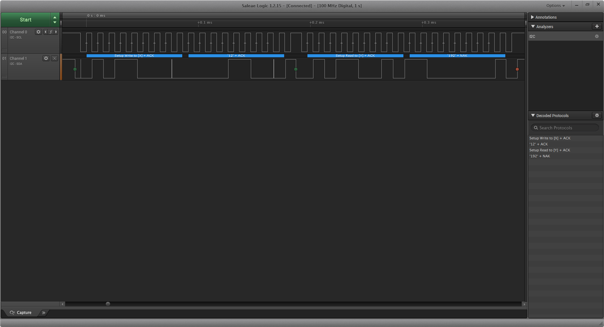
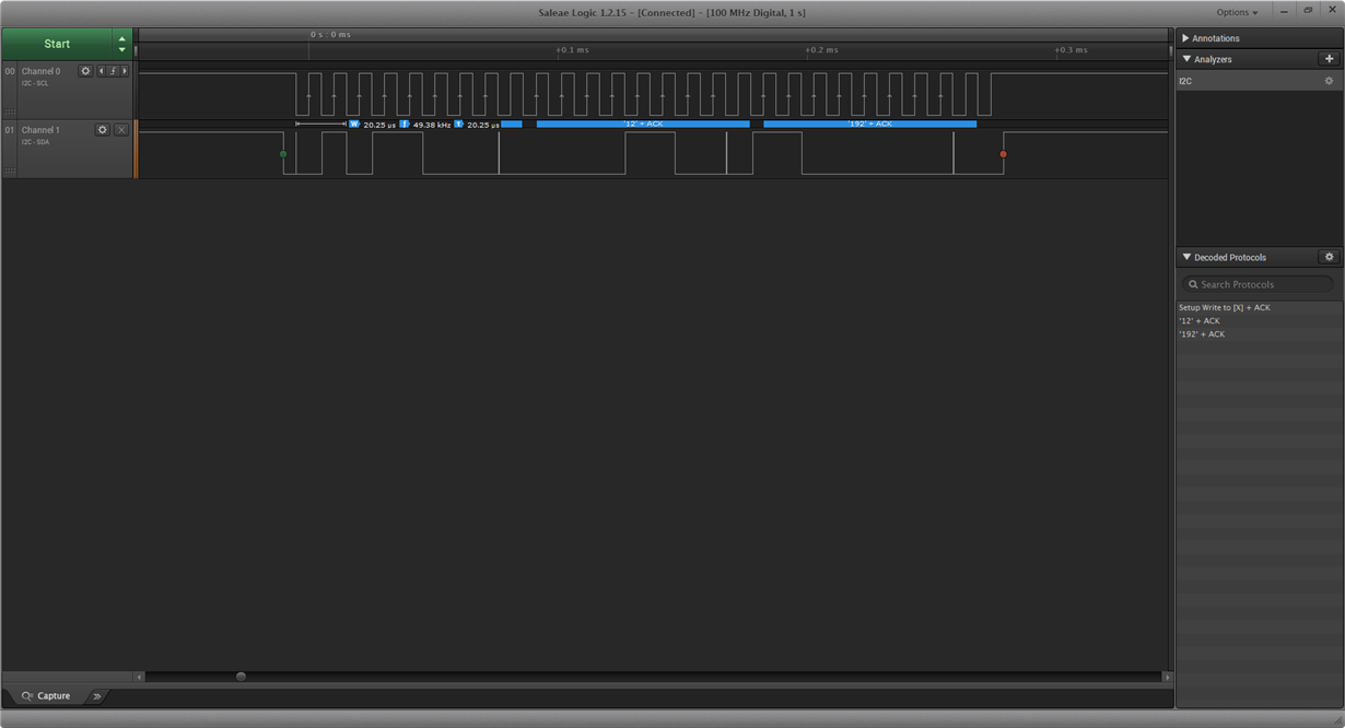
    Thank you for shipping the board to me. I reviewed your schematic and your board. I do not see any issue. The LM96194 provides two registers of 8-bit in order to form 16-bit register. So, in this case the PWM1 contains 9-bit register which contains high byte and low byte. In order to prevent any discrepency when reading or writing the value, there is a reading and writing scheme that you must consider. Any register is greater than 8-bit, the value must written into the low byte first before you can write to the high byte. Writing to the low byte first will lock the value of high byte. It is very similar to reading from the device as well.

    Please refer to page 30 of the datasheet for more detailed information.

    Let me know if you want me to ship your board back.

    Aaron
  • Hi David,

    I forgot to attach the snapshot.

    Hope this helps. Let me know you have further question.

    Read:

    Write:

    Aaron