This thread has been locked.

If you have a related question, please click the "Ask a related question" button in the top right corner. The newly created question will be automatically linked to this question.

TMP175: Pointer register and temperature conversion

Part Number: TMP175
Other Parts Discussed in Thread: TMP75B

Hello,

I am attempting to use the tmp175 with a tm4c123 tiva series microcontroller. This is my first i2c undertaking. I currently have it set for the 100kbps for easy scope captures. 

I have the device configured to read out 12 bit resolution. I have a question about the use of the pointer register and reading the 2 bytes of temperature data out. 

According to the data sheet, there is a 220ms conversion rate for the 12 bit resolution. When is a conversion triggered? 

Also, I currently write the pointer register to the temperature block (0x00) end the transmission. Immediately I do a 2 byte register read. When debugging my code, sometimes it seems correct. Other times it seems very off. Is that the correct sequencing?

The datasheet for the tmp175 is lacking implementation help.

Thanks

  • Hi Jeff,

    Figure 9 shows a temperature read transaction. The pointer register should be set using a write transaction before starting a read transaction. The pointer register will be retained by the slave device and shouldn't be necessary to write every time if you wish to re-read the same register. Since you said you're new to I2C, I'd like to point out that some slave devices won't retain the pointer at all, and require the master to Start-Address-Write-ACK-Pointer-ACK-RepeatedStart-Address-Read-ACK-Byte1-etc in one burst of communication. Additionally, some slave devices will auto-increment the pointer to the next memory location after each successful read of a byte. This enables you to read large chunks of an EEPROM, for example, in one read transaction. Our TMP devices don't have either of these features. The pointer will be retained until it is changed by another write transaction or power cycle. Hopefully that helps to clear up any confusion you might have about the pointer register.

    When SD=0 in the configuration register, the TMP175 will take measurements continuously. This means another 220ms conversion will start each time one is completed. Our modern sensors, such as TMP75B, save power by having significantly shorter conversion times, and spending most of their time in an idle state. The TMP75B can be configured to start a conversion four times per second with an average current consumption of 6.5uA. This is almost a 10x savings in current consumption over the TMP175 at roughly the same update rate.

    Thanks,
    Ren
  • Hi Ren,

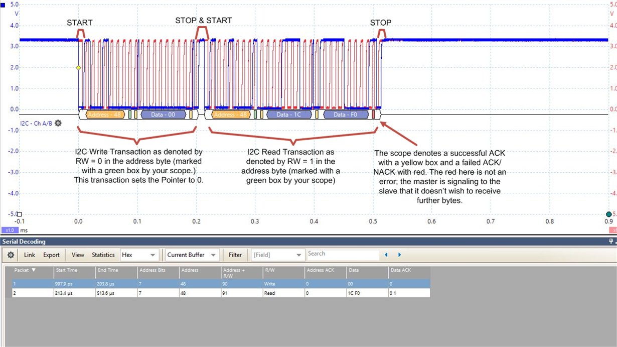
    I looked over the diagram. What I don't understand is the second group of messages where SCL and SDA are continuing. Is writing to the pointer and register and then reading it done in a single I2C instance? I believe I place a stop command on the bus. Please see the included scope screen shot. I have also included a screenshot of my configuration command. 

    What I seem to have is it works sometimes and other times I get weird readings back. The most frustration aspect of it is the bad readings (i.e. readings that appear way off) is it never triggers my scope. There may be something there, but I am still digging into that. For now, I am wondering if these screen shots give any insight to the trained eye. 

    Thanks!

    Jeff

  • Hi Jeff,

    I marked up one of your images to help you understand what's going on. You have the correct sequence in this image. Your other image shows only a read transaction. As I explained before, performing only a read transaction will work, because our device retains the pointer. However, it would be best practice to always use the sequence in the first image where you set the pointer before you read from the device.

    Thanks,

    Ren

  • Hi Ren,

    I believe my second image is only a WRITE (not read) of the configuration register. I do that in a single sequence. Write the pointer register to 0x01 and then immediately configure it for 12 bit resolution. That is at least my intention. Can you confirm?

    I appear to be incorrectly handling some error conditions within the Tiva drivers. I'll need to dig into that a bit more. More to come!

    Jeff

  • Jeff,

    You're right; the second image is a write transaction. The value 0x60 is written into the Configuration register. This value does indicate 12 bit resolution as intended.

    Thanks,
    Ren
  • Hey Ren,

    I am fully up and running. I had a missing I2CBusy function call. This, for reasons I do not understand, allowed me to successfully read the temperature 9/10 but fail periodically. Adding this additional line, along with your confirmation of correct messaging schemes and things are looking very promising. I ran overnight without issue.

    Thanks again,

    Jeff