This thread has been locked.

If you have a related question, please click the "Ask a related question" button in the top right corner. The newly created question will be automatically linked to this question.

LMT01: I have a question about the self-heating of the LMT01.

Part Number: LMT01

Hello

I am currently developing a temperature controller using the LMT01.

However, the temperature values because it is self-heating errors.

I'm trying to reduce the self-heating

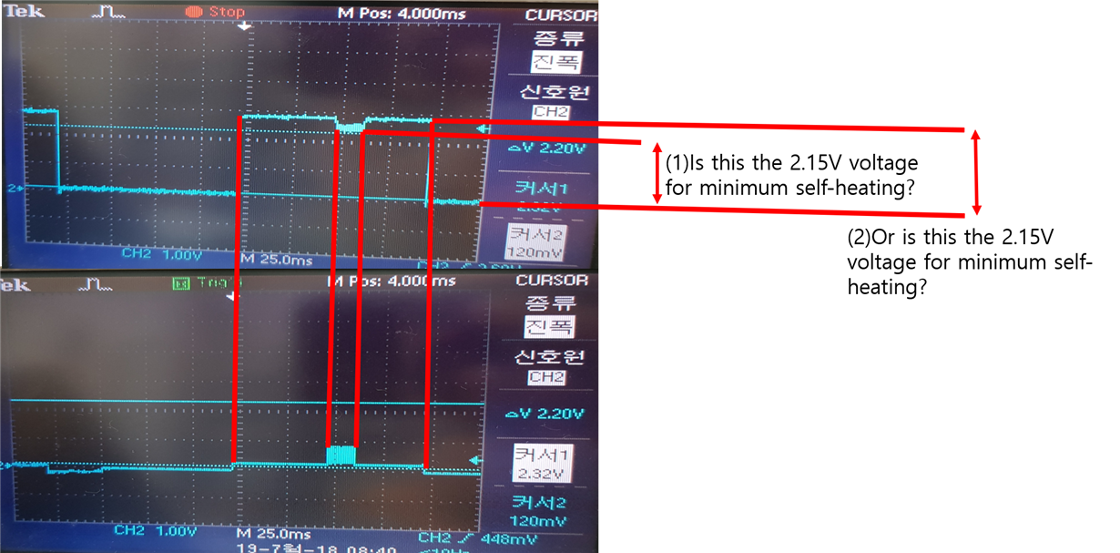
Which part should I see as the VP-VN voltage 2.15V as shown in the following figure?

(1) or (2)??

Thank you

  • Hi user,

    Can you share schematic?

    The 2V minimum is across VP-VN. It looks like you've probed VP and VN separately, referenced to ground. The 2V minimum is the difference between these waveforms.

    The LMT01 needs at least 2V to operate. When powered, it will spend 50ms making a temperature measurement, and the following 50ms it will generate pulses. It looks like you've captured this activity on your oscilloscope. You'll need to count the pulses to retrieve the temperature.

    Thanks,
    Ren
  • Replies to Ren Schackmann:

    Hi

    In the above oscilloscope picture, the above picture is the VP-VN picture and the picture below is the GND-VN picture.

    AND GND-VP inputs 3V.

    This picture is a schematic.

    What I would like to ask is, can you tell me where to look at the oscilloscope to match 2.15V for self-heating?


    Thank you

  • Hi user,

    Could you take a look at the system examples in the LMT01 datasheet, page21? It seems you've made a mistake connecting your transistor. As you've drawn it, it seems you are using it to turn the LMT01 on and off. Is this intentional?

    You'll need to monitor the voltage across the VP-VN pins and count the pulses to receive temperature. It doesn't seem like you've provided a connection for this. In the datasheet examples, the transistor is used to shift the logic levels of the pulses so they can be read correctly by the MCU. Your transistor doesn't perform this function as wired.

    You're also consuming a significant amount of current in your resistor divider R111-R112. If your circuit feels warm, it is due to this resistor divider and not the LMT01.

    Thanks,
    Ren
  • Hello

    The reason for using the transistor is because of the distribution of the voltage.

    We are currently using 5V.

    It is controlled by making 3V as transistor and distribution resistance value.

    Measure the temperature by counting the number of pulses through the VN pin.

    This is the circuit on the bottom of page 21.

    The frequency divider is 1 (100Ohm): 1.5 (150Ohm), so the 5V input is made to 3V and can be changed.

    Thank you